Continuous trapping and generating apparatus for carbon dioxide in cement kiln flue gas

A carbon dioxide and cement kiln technology, applied in carbon capture, cement production, steam engine installations, etc., to achieve the effect of simple equipment, small investment, and reduced capture costs

Active Publication Date: 2017-07-04
长沙紫宸科技开发有限公司
View PDF9 Cites 4 Cited by
  • Summary
  • Abstract
  • Description
  • Claims
  • Application Information

AI Technical Summary

Problems solved by technology

[0014] The technical problem to be solved by the present invention is to provide a cement production line that utilizes the characteristics of the process equipment of the cement production line, uses all kinds of waste heat generated in the cement production proc

Method used


Image

  • Continuous trapping and generating apparatus for carbon dioxide in cement kiln flue gas
  • Continuous trapping and generating apparatus for carbon dioxide in cement kiln flue gas
  • Continuous trapping and generating apparatus for carbon dioxide in cement kiln flue gas

Examples


Embodiment 1

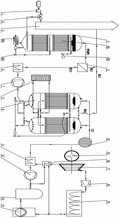
[0037] refer to figure 1 , a method suitable for CO in cement kiln flue gas 2 Continuous capture and CO 2 The power generation device mainly includes tail exhaust fan 1, electric three-ventilation valve 2, chimney 3, flue gas oxidation purifier 4, membrane separation device 5, cooler 6, flue gas compressor 7, CO 2 Circulation capture tower 8, waste heat energy storage device 9, dehydration dryer 10, CO 2 Cooler 11, CO 2 Compressor 12, liquefied CO2 storage tank 13, CO 2 High pressure pump 14, CO 2 Energy storage device 15, flow stabilizer 16, turbine 17, regenerator 18 and generator 19, the electric three-ventilation valve 2 is arranged in the flue gas between the exhaust fan 1 and the chimney 3 connected to the kiln tail dust collector On the pipeline, the air outlet of the tail exhaust fan 1 is connected with the air inlet of the electric three-ventilation valve 2, and the first exhaust port of the electric three-ventilation valve 2 is connected with the flue gas inlet ...

Embodiment 2

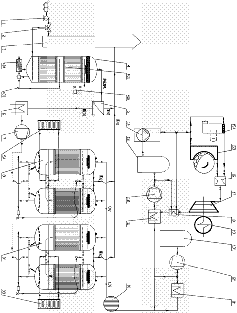
[0043] refer to figure 2 , a cement kiln flue gas containing 2 sets of CO 2 Circulation capture tower parallel capture, 2 sets of CO 2 The energy storage device is used in parallel to generate power, mainly including tail exhaust fan 1, electric three-ventilation valve 2, chimney 3, flue gas oxidation purifier 4, membrane separation device 5, cooler 6, flue gas compressor 7, CO 2 Circulation capture tower 8, the second CO 2 Circulation capture tower 8ˊ, head row exhaust gas energy storage device 9A, kiln tail exhaust gas energy storage device 9B, dehydration dryer 10, CO 2 Cooler 11, second CO 2 Cooler 11', CO 2 Compressor 12, second CO 2 Compressor 12′, liquefied CO2 storage tank 13, second liquefied CO2 storage tank 13′, CO 2 High pressure pump 14, kiln tail smoke chamber CO 2 Energy storage device 15A, kiln head cover CO 2 Energy storage device 15B, flow stabilizer 16, turbine 17, regenerator 18 and generator 19, the electric three-ventilation valve 2 is set in the...

Embodiment 3

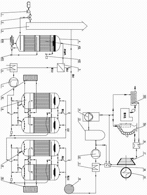
[0048] refer to image 3 , including 2 sets of CO 2 Circulation capture towers connected in series for CO in cement kiln flue gas 2 The equipment system for continuous capture and power generation mainly includes tail exhaust fan 1, electric three-ventilation valve 2, chimney 3, flue gas oxidation purifier 4, membrane separation device 5, cooler 6, flue gas compressor 7, CO 2 Circulation capture tower 8, the second CO 2 Circulating collection tower 8ˊ, kiln body energy storage device 9C, head exhaust gas energy storage device 9D, dehydration dryer 10, CO 2 Cooler 11, CO 2 Compressor 12, liquefied CO 2 Storage tank 13, CO 2 High pressure pump 14, preheater material CO 2 Energy storage device 15C, built-in CO in grate cooler 2 Energy storage device 15D, current stabilizer 16, turbine 17, generator 19 and regenerator 18, the electric three-ventilation valve 2 is placed in the flue gas between the exhaust fan 1 connected to the kiln tail dust collector and the chimney 3 On...


PUM


Abstract

The invention relates to a continuous trapping and generating apparatus for carbon dioxide in cement kiln flue gas. The apparatus comprises a tail exhaust fan, an electric three-way air valve, a chimney, a flue gas oxidation purifier, a membrane separation apparatus, a cooler, a flue gas compressor, a CO2 cyclic capturing tower, a waste heat energy-storage apparatus, a dehydration drier, a CO2 cooler, a CO2 compressor, a liquefied CO2 storage tank, a CO2 high-pressure pump, a CO2 energy-storage apparatus, a current stabilizer, a turbine, a generator and a heat regenerator. The apparatus can realize the requirement of external zero power consumption to cement production, is benefit for realizing a circular economy target of four zeros with one negative for cement enterprises, can greatly reduce the exhaust gas, exhaust water, waste heat and dust pollution on environment during a cement production process, and can effectively realize the effective emission reduction and low carbon production for cement production.

Description

technical field [0001] The present invention relates to the field of environmental protection, low-carbon and energy technologies, and in particular to a cement production line utilizing the characteristics of the process equipment of the cement production line and the characteristics of the flue gas components, and using the waste waste heat energy generated in the cement production process and / or the high-temperature heat energy that causes adverse effects as the main energy source. CO 2 A device for continuous capture and power generation. Background technique [0002] Climate change has become one of the issues affecting human survival and development, and industrial emissions of carbon dioxide are considered to be the main cause of climate warming. my country, as the largest developing country in the world, uses coal as its primary energy and fire The secondary energy structure dominated by power generation, with the rapid growth of economic aggregate, the CO of primary...

Claims


Application Information

Patent Timeline
IPC IPC(8): B01D53/78B01D53/22B01D47/06F27D17/00F01K7/32F01K17/04F01D15/10
CPCB01D47/06B01D53/228B01D53/78F01D15/10F01K7/32F01K17/04F27D17/004B01D2258/0283B01D2258/0233B01D2257/40B01D2257/302B01D2257/70B01D2257/60B01D2257/504B01D2257/2066B01D2257/2064B01D2256/10F27D2017/007Y02E20/14Y02P70/10
Inventor 尹小林
Owner 长沙紫宸科技开发有限公司
Why Eureka
Try Eureka