

A kind of magnetic particle, preparation method and application thereof
A magnetic particle and magnetic technology, applied in chemical instruments and methods, other chemical processes, special treatment targets, etc., to achieve the effect of recycling and reducing the chance of rusting
- Summary
- Abstract
- Description
- Claims
- Application Information
AI Technical Summary
Problems solved by technology
Method used
Image

Examples
Embodiment 1
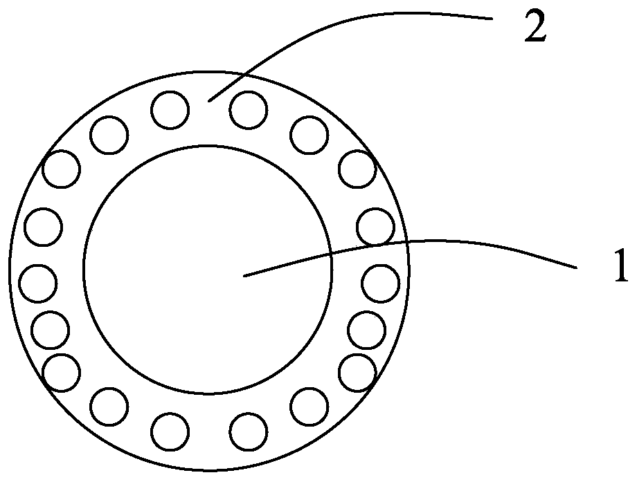
[0035] A magnetic particle, comprising a magnetic core 1 and a porous shell 2 coated on the outside of the core; the core 1 is composed of trimethylbenzene, Fe 3 o 4 and SPAN80; the shell 2 is prepared from DAROCUR 1173, polyethylene glycol dimethacrylate, dimethyl phthalate and SPAN80.
[0036] A method for preparing magnetic particles, comprising the steps of:
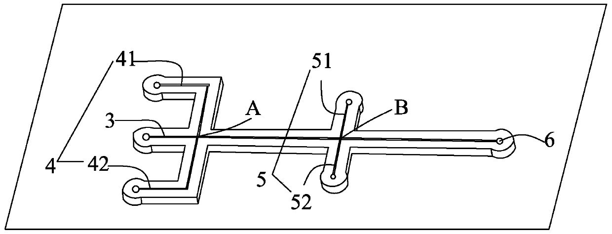
[0037] 1) By soft photolithography, prepare a microfluidic chip in which channels with a two-stage copolymerization flow structure are connected in series; the microfluidic chip includes an inner channel 3, a middle channel 4, an outer channel 5, and an outflow channel 6; The fluidic chip material is an acrylic plate, the chip is 10cm long, the microchannel is 500 μm wide, and 500 μm high; the middle channel 4 is located on both sides of the inner channel 3, including the first middle channel 41 and the second middle channel 42; the outer channel is located at Between the inner channel and the outflow channel, the ...
Embodiment 2
[0046] A magnetic particle, comprising a magnetic core 1 and a porous shell 2 coated on the outside of the core; the core 1 is composed of trimethylbenzene, Fe 2 o 3 and octyltrimethylammonium bromide; the shell 2 is prepared from DAROCUR 1173, polyethylene glycol dimethacrylate, dimethyl phthalate and block polyether F108 (2%wt) become.
[0047] A method for preparing magnetic particles, comprising the steps of:
[0048] 1) By soft photolithography, prepare a microfluidic chip in which channels with a two-stage copolymerization flow structure are connected in series; the microfluidic chip includes an inner channel 3, a middle channel 4, an outer channel 5, and an outflow channel 6; The fluidic chip material is an acrylic plate, the chip is 10cm long, the microchannel is 500 μm wide, and 500 μm high; the middle channel 4 is located on both sides of the inner channel 3, including the first middle channel 41 and the second middle channel 42; the outer channel is located at Be...
Embodiment 3
[0054] A magnetic particle, comprising a magnetic core 1 and a porous shell 2 coated on the outside of the core; the core 1 is prepared from trimethylbenzene, FeO and octyltrimethylammonium bromide; the shell 2 Prepared from DAROCUR 1173, polyethylene glycol dimethacrylate, dimethyl phthalate and SPAN80.
[0055] A method for preparing magnetic particles, comprising the steps of:
[0056] 1) By soft photolithography, prepare a microfluidic chip in which channels with a two-stage copolymerization flow structure are connected in series; the microfluidic chip includes an inner channel 3, a middle channel 4, an outer channel 5, and an outflow channel 6; The fluidic chip material is an acrylic plate, the chip is 10cm long, the microchannel is 500 μm wide, and 500 μm high; the middle channel 4 is located on both sides of the inner channel 3, including the first middle channel 41 and the second middle channel 42; the outer channel is located at Between the inner channel and the outf...
PUM
 Abstract
Description
Claims
Application Information