Vacuum ultraviolet light source device through coaxial gas discharge

A technology of vacuum ultraviolet light source and gas discharge, applied in gas plasma lamps, lamp parts and other directions, can solve the problems of low output optical power and low photon utilization rate, achieve high effective vacuum ultraviolet light power, increase effective area, The effect of improving the utilization rate of the light source

Active Publication Date: 2017-07-11
PLA PEOPLES LIBERATION ARMY OF CHINA STRATEGIC SUPPORT FORCE AEROSPACE ENG UNIV
View PDF8 Cites 9 Cited by
  • Summary
  • Abstract
  • Description
  • Claims
  • Application Information

AI Technical Summary

Problems solved by technology

[0005] The invention overcomes the disadvantages of low photon utilization rate and low output light power of the traditional vacuum ultraviolet light source, adopts the method of exciting gas plasma in a spiral resonant cavity, and provides a radio frequency discharge lamp structure

Method used


Image

  • Vacuum ultraviolet light source device through coaxial gas discharge
  • Vacuum ultraviolet light source device through coaxial gas discharge

Examples


specific Embodiment approach 1

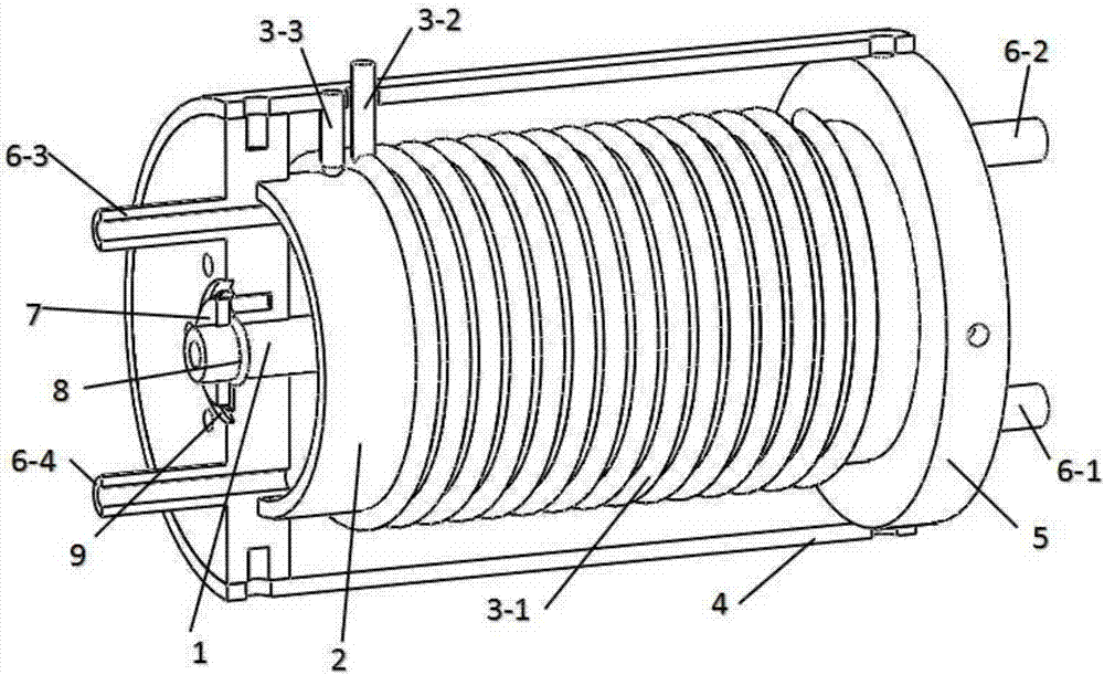
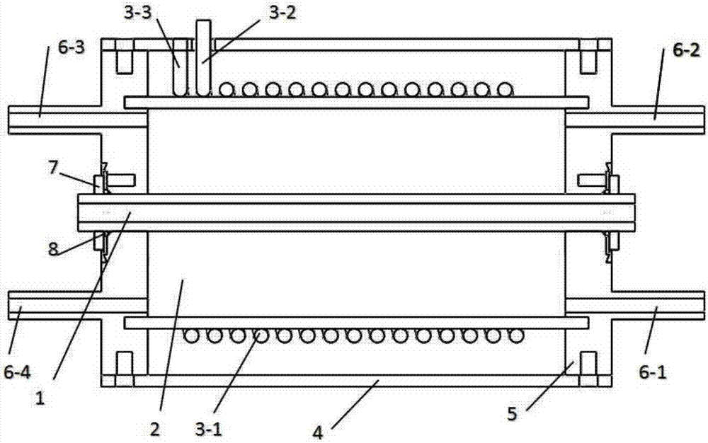
[0017] Specific implementation mode one: combine figure 1 To illustrate this embodiment, the overall structure of the coaxial gas discharge vacuum ultraviolet light source device described in this embodiment includes a central cylindrical interaction cavity, a coaxial annular discharge light source cavity, a radio frequency spiral resonance excitation cavity and an ultra-high vacuum flange connector. part. The specific implementation steps are as follows: first, the solenoid coil 3 is sleeved on the outside of the quartz glass tube 2, and bonded in the installation groove of the flange connector 5 with an adhesive that can be used in an ultra-high vacuum environment, so as to realize the connection between the outer wall of the discharge light source cavity and Atmospheric vacuum sealing, the length of the quartz glass tube determines the overall length reference of the entire device; secondly, the copper shielding layer 4 is installed on the outside of the solenoid coil 3 in ...

specific Embodiment approach 2

[0018] Specific embodiment two: this embodiment is a further limitation of the coaxial gas discharge vacuum ultraviolet light source device described in embodiment one, combined with figure 1 This embodiment will be described. In this embodiment, the gas conduit 6 on the flange connector 5 can be increased or decreased as required. By adjusting the switch mode of the gas conduit 6, switching between different working states of flowing gas and non-flowing gas can be realized: the working gas in the flowing gas state has There are also inlets and outlets. When the vacuum ultraviolet lamp is working, the gas is in a dynamic balance in the discharge light source cavity; according to the way of inlet and outlet, it can also be divided into forward flow (6-1 is the inlet, 6-3 is the outlet) and countercurrent (6-1 for import, 6-2 for export). When working in a non-flowing state, the gas is sealed inside the cavity of the discharge light source and is in a static state.

specific Embodiment approach 3

[0019] Embodiment 3: This embodiment is a further limitation of the coaxial gas discharge vacuum ultraviolet light source device described in Embodiment 1. In this embodiment, according to the needs of practical applications, the discharge light source chamber can be filled with Helium, neon, argon, krypton, xenon and other different working gases or mixed gases are used to generate vacuum ultraviolet light with different wavelengths; by adjusting the gas pressure in the discharge light source cavity and the frequency and power of the RF signal in the spiral resonant cavity, etc., The output power of the vacuum ultraviolet light can be adjusted to meet the needs of different applications for the light source.


PUM


Abstract

The invention adopts a radio frequency gas discharge manner to excite the inert gas plasmas and provides a device for generating a vacuum ultraviolet light source. The device comprises four parts: a central cylindrical shaped interaction cavity, a coaxial circular power charge light source cavity, a radio frequency spiral resonance excitation cavity and an ultrahigh vacuum flange connection component. The device uses a circular tube made of magnesium fluoride crystal materials as its optical window; the vacuum ultraviolet light is generated in the coaxial circular power charge light source cavity on the outer wall of magnesium fluoride circular tube, then penetrates and is radiated into the central cylindrical shaped interaction cavity so that the light could act on a target material directly. In this manner, the travel distance of the light rays is shortened; the effective size of the light source is increased; the beam-divergence angle is reduced; and the utilization efficiency of the light source is increased. According to the invention, the device adopts an electrodeless radio frequency charge manner to excite the gas plasmas, and produces vacuum ultraviolent photons with specific wavelengths by filling different inert gases. Through the adjustment of the parameters of the gases like gas pressure, radio frequency and power, it is possible to adjust the output power of the vacuum ultraviolet light so as to meet the requirements of various applications on the light source.

Description

technical field [0001] The invention relates to a coaxial gas discharge vacuum ultraviolet light source device, which is used in the fields of vacuum ultraviolet spectroscopy measurement, vacuum ultraviolet photochemical analysis, vacuum ultraviolet spectroscopy and the like. Background technique [0002] Vacuum ultraviolet light is a kind of high-energy photon, which can cause the energy level transition and chemical reaction of atoms and molecules in the material near the ionization energy. Research fields, such as vacuum ultraviolet spectroscopy, vacuum ultraviolet photochemistry, vacuum ultraviolet spectroscopic analysis, etc. How to design and develop a vacuum ultraviolet light source with long working life, high luminous efficiency and high stability is the primary problem to be solved in these studies. [0003] Vacuum ultraviolet light sources can be divided into three types: DC driven gas discharge vacuum ultraviolet lamps, radio frequency driven gas discharge vacuu...

Claims


Application Information

Patent Timeline
IPC IPC(8): H01J63/08H01J63/02
CPCH01J63/02H01J63/08
Inventor 洪延姬冯高平王明东王广宇宋俊玲
Owner PLA PEOPLES LIBERATION ARMY OF CHINA STRATEGIC SUPPORT FORCE AEROSPACE ENG UNIV
Why Eureka
Try Eureka