Method for continuously catching CO2 in cement kiln flue gas with hydrate method

A cement kiln and hydrate technology, applied in separation methods, chemical instruments and methods, gas treatment, etc., can solve the problems of inability to achieve continuous absorption, insufficient separation capacity, and low degree of energy saving.

Active Publication Date: 2017-07-18
长沙紫宸科技开发有限公司
View PDF10 Cites 7 Cited by
  • Summary
  • Abstract
  • Description
  • Claims
  • Application Information

AI Technical Summary

Problems solved by technology

This hydrate method has no serious secondary pollution caused by the traditional chemical adsorption method or physical chemical adsorption method, but there are still the following problems: it needs to react for several hours in a closed high-pressure reactor under high-pressure stirring, and the reaction time for hydrate formation It is still too long; the hydration reaction needs to be carried out under electromagnetic stirring in a closed high-pressure container, and the continuous absorption of CO in the flue gas flow cannot be achieved. 2 ; Produced CO 2 The energy consumption of compressing into a liquid state is too high, and the separation capacity is insufficient
The device uses boiler recovery waste heat as energy to reduce CO in cement kiln exhaust gas 2 The capture of a large amount of high temperature and high pressure waste heat is not well utilized, and the degree of energy saving is not high, which has certain limitations

Method used


Image

  • Method for continuously catching CO2 in cement kiln flue gas with hydrate method
  • Method for continuously catching CO2 in cement kiln flue gas with hydrate method
  • Method for continuously catching CO2 in cement kiln flue gas with hydrate method

Examples


Embodiment 1

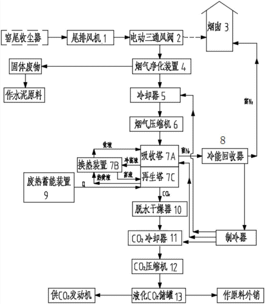
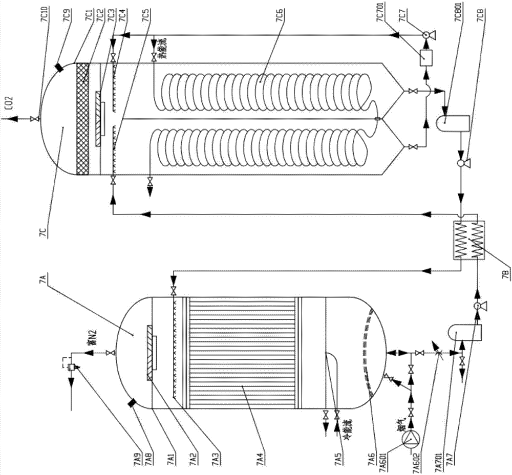
[0054] like Figures 1 to 3 As shown, the tail exhaust fan 1 connected to the dust collector at the kiln tail continuously sends the flue gas into the flue gas pipe, and the electric three-ventilation valve 2 is set on the flue gas pipe between the tail exhaust fan 1 connected to the dust collector at the kiln tail and the chimney 3 , the flue gas enters the flue gas purification device 4 through the first exhaust port of the electric three-ventilation valve 2, and the purified flue gas separated from the flue gas purification device 4 enters the cooler 5 for cooling, and then enters the flue gas compressor 6 for further processing. Compression, the compressed purified flue gas enters the CO 2 Absorption tower - regeneration tower unit, the purified flue gas in CO 2 Absorption of CO from the regeneration unit 2 In the absorption tower 7A, from the inlet of the gas distribution and liquid discharge device 7A6 at the bottom of the absorption tower 7A, it flows upwards through ...

Embodiment 2

[0061] When the dust content of the flue gas from the dust collector at the end of the kiln of the cement plant is lower than 20mg / nm 3 And when there are no heavy metal pollutants, the difference from Example 1 is that the flue gas purification treatment step is canceled, the flue gas exiting the dust collector at the end of the kiln is suctioned and blown in by the tail exhaust fan, and the electric air valve is switched and sent to the cooler for cooling. Compressed continuously by compressor and sent to CO 2 Continuous capture of CO by hydrate method in absorption tower 2 .

Embodiment 3

[0063] During processing, in order to be able to provide more pure CO 2 , the difference from Example 1 is: using another CO in series 2 Absorber - Regenerative Tower Unit, Even More CO 2 Absorption tower - regeneration tower unit.


PUM


Abstract

The invention provides a method for continuously catching CO2 in cement kiln flue gas with a hydrate method. The method comprises the following steps: continuously catching, curing, separating CO2 in continuously-flowing flue gas stream by taking a hydrate promoter solution as a catching agent and taking a large amount of waste residual heat generated in a cement production process as an energy source through a CO2 absorbing tower-regeneration tower unit comprising a silk screen catching bed device, and enriching a CO2 hydrate and continuously separating and discharging N2-enriched gas flow to realize continuous catching; continuously enriching caught CO2 hydrate rich liquor, transferring the enriched CO2 hydrate rich liquor into a regeneration tower for performing continuous separating and releasing to obtain continuous CO2 gas flow, and recycling hydrate poor liquor obtained by continuous separating and releasing; drying, cooling, compressing and storing the CO2 being subjected to continuous separating and releasing. By adopting the method, the CO2 in the cement kiln flue gas is continuously caught efficiently at low cost by using a part of process equipment on a cement production line and waste residual heat generated in the cement production process, so that the technical problem that only intermittent high-pressure air-tight catching is available and continuous catching is unavailable in a process of catching CO2 with a hydrate is solved.

Description

technical field [0001] The invention relates to the field of environmental protection and low-carbon technology, in particular to a hydrate method for continuously capturing CO in cement kiln flue gas 2 Methods. Background technique [0002] Climate change has become one of the issues affecting human survival and development, and carbon dioxide emitted by industry is considered to be the main cause of climate warming. As the largest developing country in the world, our country uses coal as its primary energy and thermal power as its secondary energy as its energy structure. With the rapid growth of economic aggregate, the CO of primary energy and secondary energy 2 Emissions have the characteristics of fast growth and large total volume, but the high investment and high capture cost of the current carbon emission reduction and climate change CCS or CCUS technology have become a serious obstacle to popularization and application. The existing research and demonstration app...

Claims


Application Information

Patent Timeline
Patent Type & Authority Applications(China)
IPC IPC(8): B01D53/62B01D53/96B01D53/79
CPCB01D53/343B01D53/62B01D53/96B01D2257/504B01D2258/0233B01D2259/124Y02A50/20Y02C20/40
Inventor 尹小林
Owner 长沙紫宸科技开发有限公司
Why Eureka
Try Eureka