
Cantilever beam type membrane stress power generation structure

A thin-film pressure, cantilever beam technology, applied in the field of micro-electromechanical systems, can solve problems such as kinetic energy not being used, not conforming to the principles of energy conservation and environmental protection, etc.

Inactive Publication Date: 2017-07-21
ZHONGBEI UNIV
View PDF9 Cites 5 Cited by
  • Summary
  • Abstract
  • Description
  • Claims
  • Application Information

AI Technical Summary

Problems solved by technology

[0003] At present, devices such as scoreboards and lighting equipment in sports competitions such as taekwondo and martial arts performances work through external power supplies, which do not meet the principles of energy conservation and environmental protection. The kinetic energy consumed by athletes on the field is not utilized. The present invention For this problem, a cantilever beam type membrane pressure power generation structure is provided

Method used


Image

  • Cantilever beam type membrane stress power generation structure
  • Cantilever beam type membrane stress power generation structure
  • Cantilever beam type membrane stress power generation structure

Examples


Embodiment Construction

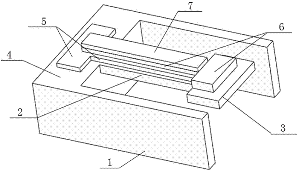
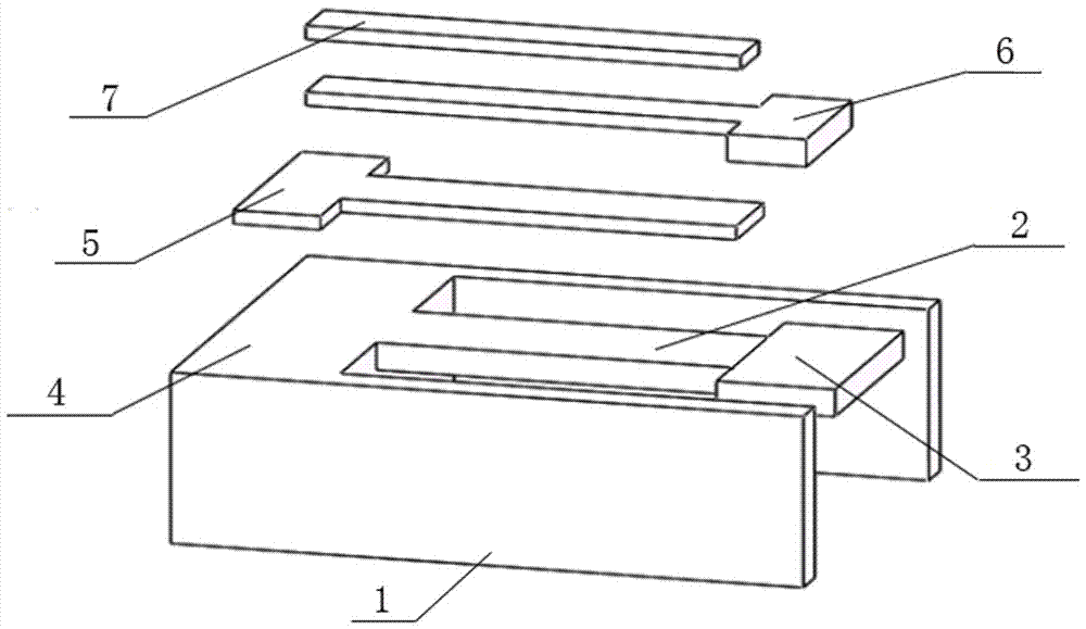
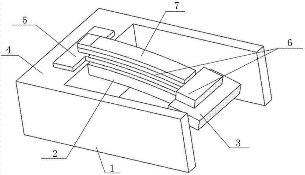
[0018] A cantilever beam type thin-film pressure power generation structure, comprising a frame-shaped base 1, one side opening of the frame-shaped base 1, a silicon cantilever beam 2 suspended in the frame-shaped base is arranged on the beam facing the opening of the frame-shaped base, the silicon cantilever The free end of the beam 2 is fixed with a mass block 3, the width of the mass block 3 is greater than the width of the silicon cantilever beam 2, and a silicon dioxide insulating layer 4 is arranged on the beam facing the opening of the frame-shaped base. A Pt / Ti (platinum-plated on titanium) bottom electrode layer 5 is provided. On the Pt / Ti bottom electrode layer 5, there is a strip-shaped Pt / Ti bottom electrode layer 5 located above the silicon cantilever beam extending toward the opening side of the frame-shaped base. The mass block A PZT piezoelectric layer 6 is arranged on it, and the PZT piezoelectric layer 6 extends toward the silicon dioxide insulating layer with...


PUM

PropertyMeasurementUnit
Resonant frequencyaaaaaaaaaa

Abstract

The invention belongs to the field of Micro-Electro-Mechanical System (MEMS), more specifically, the invention relates to a cantilever beam type membrane stress power generation structure, which comprises a frame type substrate, wherein a silicon cantilever beam suspended in the frame type substrate is positioned on a beam facing an opening of the frame type substrate, the free end of the silicon cantilever beam is fixedly provided with a mass block, a silicon dioxide insulation layer is also positioned above the beam facing the opening of the frame type substrate, a bottom electrode layer is positioned on the silicon dioxide insulation layer, a strip bottom electrode layer positioned above the silicon cantilever beam extends on the bottom electrode layer in the direction towards the opening of the frame type substrate, a PZT piezoelectric layer is positioned on the mass block, a strip PZT piezoelectric layer positioned above the strip bottom electrode layer extends on the PZT piezoelectric layer in the direction towards the silicon dioxide insulation layer, and a top electrode layer is positioned above the strip PZT piezoelectric layer. When the system is in a vibration environment, the vibration in the external environment can be transferred to the system, vibration and bending deformation of the silicon cantilever beam are caused, mechanical energy is stored in the silicon cantilever beam, thereby, the piezoelectric layer is stretched and contracted and an electrical signal is generated, and the conversion of mechanical energy to electrical energy is realized.

Description

technical field [0001] The invention belongs to the field of micro-electromechanical systems, and in particular relates to a cantilever beam type film pressure power generation structure. Background technique [0002] Micro-Electro-Mechanical System (MEMS) technology is based on microelectronics technology, a revolutionary new technology that intersects multiple disciplines such as sound, light, electricity, materials, mechanics, and chemistry. It adopts semiconductor processing technology, integrates key technologies such as lithography, corrosion, etching, and deposition, and is committed to creating ultra-miniature smart chips that integrate sensors, actuators, and micro-energy. MEMS technology gradually evolved from microelectronics technology in the process of developing silicon microsensors, and was initially applied to silicon piezoresistive pressure sensors. With the development and promotion of this technology, various silicon-based sensors prepared by using MEMS t...

Claims


Application Information

Patent Timeline
Patent Type & Authority Applications(China)
IPC IPC(8): B81B3/00B81C1/00
CPCB81B3/0021B81B3/0037B81B2203/0118B81C1/00158B81C1/00349B81C2201/0101B81C2201/0174
Inventor 闫树斌李国洪张志东张彦军冯登超张勐赵学峰薛晨阳张文栋
Owner ZHONGBEI UNIV
Learn More