Negative electrode current collector and fabrication method thereof and application

A current collector and negative electrode technology, which is applied in the field of negative electrode current collectors, can solve the problems of reducing the service life of lithium-ion batteries, copper plating shedding, copper plating shedding, etc. Effect

Inactive Publication Date: 2017-07-25
SHENZHEN XINZHIMEI TECH CO LTD
View PDF0 Cites 38 Cited by
  • Summary
  • Abstract
  • Description
  • Claims
  • Application Information

AI Technical Summary

Problems solved by technology

However, the thickness of its copper plating is as high as 1.5μm (a certain thickness is required to achieve satisfactory conductivity), which is much thicker than the thickness of the copper plating film of traditional packaging materials, and the thicker the plating, the better the copper plating. The easier the layer comes off the plastic
[0004] In addition, the surface of the copper

Method used


Image

  • Negative electrode current collector and fabrication method thereof and application

Examples


Embodiment 1

[0038] A preparation method of a negative electrode current collector, comprising the steps of:

[0039] S1. First, corona treatment is performed on the surface of the plastic film to be coated, and then the reel plastic film is placed in the vacuum chamber of the double-sided reciprocating magnetron sputtering coating machine, the vacuum chamber is sealed, and the vacuum is gradually evacuated until the vacuum degree reaches 3× 10⁻³ -6×10 -3 Pa, double-sided back-and-forth high-efficiency coating on the plastic film by magnetron sputtering, the target material is nickel, the purity is ≥99.9%, adjust the unwinding speed and winding speed, and the sputtered nickel atoms form a layer on the moving film Nickel-plated layer, that is, the adhesion-enhancing layer;

[0040] S2. Put the nickel-plated film obtained in S1 into the vacuum chamber of the double-sided reciprocating evaporation coating machine, seal the vacuum chamber, and evacuate step by step until the vacuum degree rea...

Embodiment 2

[0044] A preparation method of a negative electrode current collector, comprising the steps of:

[0045] S1. First, corona treatment is performed on the surface of the plastic film to be coated, and then the reel plastic film is placed in the vacuum chamber of the double-sided reciprocating magnetron sputtering coating machine, the vacuum chamber is sealed, and the vacuum is gradually evacuated until the vacuum degree reaches 3× 10 -3 -6×10 -3 Pa, double-sided back-and-forth high-efficiency coating on the plastic film by magnetron sputtering, the target material is nickel, the purity is ≥99.9%, adjust the unwinding speed and winding speed, and the sputtered nickel atoms form a layer on the moving film Nickel-plated layer, that is, the adhesion-enhancing layer;

[0046] S2. Put the nickel-plated film obtained in S1 into the vacuum chamber of the double-sided reciprocating evaporation coating machine, seal the vacuum chamber, and evacuate step by step until the vacuum degree r...


PUM

PropertyMeasurementUnit
Thicknessaaaaaaaaaa
Thicknessaaaaaaaaaa
Thicknessaaaaaaaaaa

Abstract

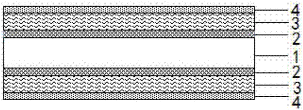
The invention discloses a negative electrode current collector and a fabrication method and application thereof. The negative electrode current collector has a multi-layer structure and comprises a plastic thin film, wherein an adhesive strength improvement layer, a copper metal plating layer and an oxidization-prevention layer are sequentially plated on an upper surface and a lower surface of the plastic thin film. The fabrication method comprises the steps of sequentially plating the adhesive strength improvement layer on the plastic thin film by a magnetron sputtering coating process, plating copper by an evaporation coating process, and plating the oxidization-prevention layer by an electron beam evaporation or magnetron sputtering coating process. The negative electrode current collector is mainly applied to a lithium ion battery. By the negative electrode current collector, the lightness of the battery can be achieved, the energy density is improved, the cost is reduced, and the copper plating layer cannot be liable to fall off and is not liable to oxidize.

Description

technical field [0001] The invention relates to a negative electrode current collector, its preparation method and application. Background technique [0002] The negative current collector of traditional lithium-ion batteries is copper foil. With the development of lithium battery technology, high energy density, light weight and flexibility of lithium ion batteries have become people's pursuit. Thinning copper foil can reduce the weight of lithium-ion batteries, increase energy density, and reduce costs. However, due to the limitations of the preparation technology, it is difficult to reduce the thickness of the copper foil (the copper foil can be mass-produced to 6 μm at present); in addition, after the copper foil is thinned, the mechanical strength decreases, resulting in a decrease in processing performance, so a new "thinning technology" is needed ". [0003] In the prior art, copper is plated on plastic (such as PET) as a current collector to increase the energy de...

Claims


Application Information

Patent Timeline
IPC IPC(8): H01M4/66H01M4/70H01M10/0525
CPCH01M4/0404H01M4/0426H01M4/661H01M4/662H01M4/664H01M4/667H01M4/70H01M10/0525C01B21/06C23C14/081C23C14/205C23C14/30C23C14/35C23C14/562C23C14/568H01M4/668H01M2004/028Y02E60/10C23C14/022C23C14/025C23C14/185C23C14/3414C08F10/06C08F14/06C01B32/956H01M10/052
Inventor 邱洪礼
Owner SHENZHEN XINZHIMEI TECH CO LTD
Why Eureka
Try Eureka