System for conveying therapeutic drugs

A technology of therapeutic drugs and buffer devices, which is applied in the field of delivery of therapeutic drugs to achieve the effect of safe operation, good wall-attachment adaptability and reduced stimulation

Active Publication Date: 2017-07-28
NINGBO DIOCHANGE MEDICAL TECH CO LTD
View PDF10 Cites 5 Cited by
  • Summary
  • Abstract
  • Description
  • Claims
  • Application Information

AI Technical Summary

Problems solved by technology

[0009] In view of this, the object of the present invention is to provide a system for delivering therapeutic drugs, which is used to solve the problem that the current injection system cannot maintain good adaptability and adherence in the process of systole and diastole

Method used


Image

  • System for conveying therapeutic drugs
  • System for conveying therapeutic drugs
  • System for conveying therapeutic drugs

Examples


Embodiment 1

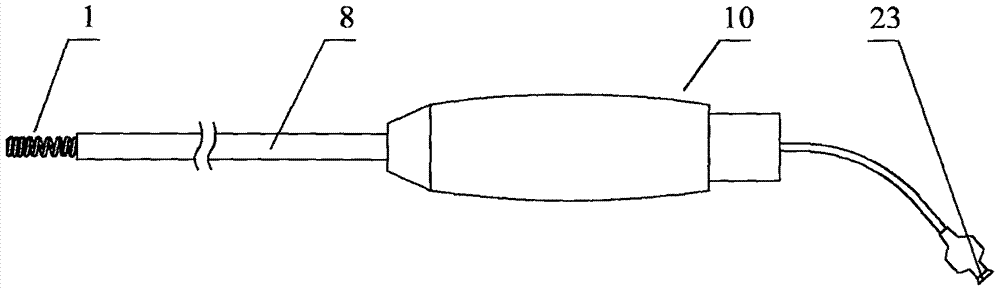
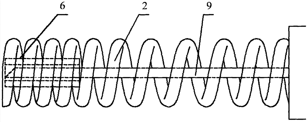
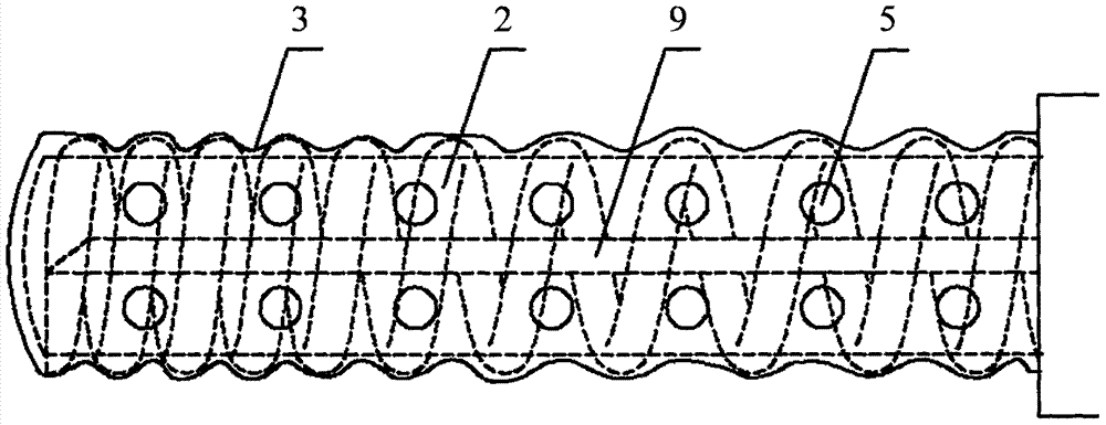
[0069] Such as Figures 1 to 2 As shown, the system for delivering therapeutic drugs provided by the present invention includes an injection catheter 8, an injection needle 9 and an operating handle 10, wherein the injection needle 9 is in fluid communication with the injection catheter 8, and the operating handle 10 is fixedly connected to the injection catheter 8 The proximal end of the injection catheter 8 is provided with a buffer device 1 , and part or all of the injection needle 9 is arranged in the buffer device 1 . In the natural state, the design that the injection needle 9 is set in the buffer device 1 can prevent the system from being pushed from outside the body to the target position, such as the entire approach process of the inner wall of the left ventricle (femoral artery → iliac artery → abdominal aorta → Thoracic aorta → aortic arch → ascending aorta → aortic valve → left ventricle), the contact between the injection needle 9 and the tissues of the human or a...

Embodiment 2

[0095] Such as Figure 12 to Figure 15 As shown, on the basis of Embodiment 1, the difference between Embodiment 2 and Embodiment 1 is that the distal end of the buffer device 1 is provided with a leak-proof device 16, and the distal surface of the leak-proof device 16 is round and smooth. As for the contact surface, the smooth contact surface may be a plane perpendicular to the centerline of the injection needle, or a convex surface that is convex toward the distal end, or a concave surface that is concave toward the proximal end. The smooth contact surface is not only conducive to the introduction and push of the injection system in the vascular access or catheter sheath, but also improves the consistent adaptability and adherence of the injection system to the systolic and diastolic movements during the injection process to prevent drug leakage. An injection needle guide rail 6 is arranged inside the leakage prevention device 16 , and the proximal end of the leakage prevent...

Embodiment 3

[0097] Such as Figure 18 and Figure 19 As shown, on the basis of embodiment 1, the difference between embodiment 3 and embodiment 1 is that the system also includes a negative pressure device, which includes a tube body arranged outside the injection needle, and the tube body The distal end of the tube body is in contact with the tissue, and the proximal end of the tube body is connected to a vacuum source. When the distal end of the tube body is pressed against the patient's tissue, a vacuum cavity is formed inside the tube body. In one embodiment, the injection catheter 8 is a double-lumen tube, one of which is a vacuum chamber 21 , and the other is a drug injection chamber 22 , and the proximal end of the drug injection chamber 22 is fixedly connected to a drug injection port 23 . The negative pressure device includes a vacuum chamber 21 arranged in the injection catheter 8 , a vacuum connecting pipe 25 fluidly communicated with the vacuum chamber 21 , a vacuum suction c...


PUM


Abstract

The invention relates to a system for conveying therapeutic drugs. The system comprises an injection catheter, an injection needle and an operating handle. The injection needle is communicated with the injection catheter via fluid, the operating handle is fixedly connected to the near end of the injection catheter, a buffer device is arranged at the far end of the injection catheter, and the injection needle is partially or completely arranged in the buffer device. When the far end of the buffer device is pressed, the axial length of the buffer device is reduced, and the needle tube of the injection needle stretches out of the buffer device. By means of the system, the risk of leakage of injection drugs is significantly lowered, the fit adaptability in the cardiac contraction and relaxation process is improved, and the probability of breakage of the injection needle is reduced; the system is simple in overall design, safe and convenient to operate and easy to use.

Description

technical field [0001] The invention relates to the technical field of medical devices, in particular to a system for delivering therapeutic drugs. Background technique [0002] Chronic heart failure (CHF) is the final destination of most cardiovascular diseases, and it is still a type of disease with high morbidity and mortality worldwide. The current statistical results show that the incidence rate of this disease among people over 45 years old in the country is 3%~ 5%. [0003] For the treatment of chronic heart failure (CHF) at the end stage, the therapeutic effects of drugs are limited, and the only clinical methods available for treatment are left ventricular assist device and heart transplantation. However, heart transplantation has been greatly limited due to the scarcity of heart donors. In order to improve the symptoms of patients with end-stage chronic heart failure and prolong the survival time of patients. Recently, a clinical study called AUGMENT HF showed t...

Claims


Application Information

Patent Timeline
Patent Type & Authority Applications(China)
IPC IPC(8): A61M5/178A61M5/31A61M5/32
CPCA61M5/178A61M5/31A61M5/3137A61M5/321A61M2005/3143A61M2205/02
Inventor 吕世文李彪葛均波李欣欣沈雳
Owner NINGBO DIOCHANGE MEDICAL TECH CO LTD
Why Eureka
Try Eureka