Preparation method of CdS/GE/Fe2O3 composite photocatalyst

A technology of catalyst and composite light, which is applied in the direction of physical/chemical process catalysts, chemical instruments and methods, chemical/physical processes, etc., can solve the problems of low photocatalytic performance and limited application range, and achieve convenient magnetic separation and reuse, excellent The effect of visible light catalytic activity

Active Publication Date: 2017-07-28
JIANGSU UNIV
View PDF4 Cites 2 Cited by
  • Summary
  • Abstract
  • Description
  • Claims
  • Application Information

AI Technical Summary

Problems solved by technology

The core of photocatalytic technology is photocatalytic materials. Traditional photocatalytic materials are metal oxides or sulfide semiconductor compounds. These materials are limited by their own properties, and their photocatalytic performance is generally low.
For example, TiO 2 It is the most widely used photocatalyst, but because its band gap energy is greater than 3.0eV, it has catalytic activity only under ultraviolet light irradiation, which greatly limits its application range.

Method used


Image

  • Preparation method of CdS/GE/Fe2O3 composite photocatalyst
  • Preparation method of CdS/GE/Fe2O3 composite photocatalyst
  • Preparation method of CdS/GE/Fe2O3 composite photocatalyst

Examples


Embodiment 1

[0023] Ultrasonic disperse 10mg of PB in 40mL of deionized water, add 2mL of PAH (1g L -1 ) solution, stirred for 3h; then sequentially added 1mL 5mg mL -1 GO solution; 5mL 0.11M CdCl 2 solution, stirred for 3h; finally added 5mL of 0.11M Na 2 S solution, stirred for 3h. After washing with deionized water, the obtained sample was placed in an argon atmosphere at 2 °C min -1 The temperature was raised to 350°C and kept for 2h to obtain the final product.

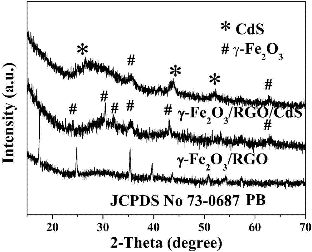
[0024] figure 1 It is the XRD pattern of the product, and all the diffraction peaks in Figure PB are consistent with JCPDS No.73-0687, corresponding to the cubic phase of Fe 4 [Fe(CN) 6 ] 3 . For γ-Fe 2 o 3 In the XRD pattern of / RGO, the diffraction peaks at 30.24, 35.63, 43.28, 53.73, 57.27, 62.925 and 62.499° correspond to (022), (311), (400), (422), (511), and (440) Crystal faces, with γ-Fe 2 o 3 The standard card (JCPDS No 39-1346) matches. In γ-Fe 2 o 3 / RGO / CdS XRD patterns, except for γ-Fe 2 o 3 The ...

Embodiment 2

[0028] Ultrasonic disperse 5 mg of PB in 40 mL of deionized water, add 2 mL of PAH (1 g L -1 ) solution, stirred for 3h; then sequentially added 1mL 5mg mL -1 GO solution; 5mL 0.11M CdCl 2 solution, stirred for 3h; finally added 5mL of 0.11M Na 2 S solution, stirred for 3h. After washing with deionized water, the obtained sample was placed in an argon atmosphere at 2 °C min -1 The temperature was raised to 350°C and kept for 2h to obtain the final product.

Embodiment 3

[0030]Ultrasonic disperse 15mg of PB in 40mL of deionized water, add 2mL of PAH (1g L -1 ) solution, stirred for 3h; then sequentially added 1mL 5mg mL -1 GO solution; 5mL 0.11M CdCl 2 solution, stirred for 3h; finally added 5mL of 0.11M Na 2 S solution, stirred for 3h. After washing with deionized water, the obtained sample was placed in an argon atmosphere at 2 °C min -1 The temperature was raised to 350°C and kept for 2h to obtain the final product.


PUM

PropertyMeasurementUnit
concentrationaaaaaaaaaa
particle diameteraaaaaaaaaa

Abstract

The invention belongs to the field of nano composite material preparation, and particularly relates to a preparation method of a CdS nanoparticle modified graphene (GE) / gamma-Fe2O3 composite photocatalyst. The preparation method mainly includes steps: using a hydrothermal method to synthesize cubic Prussian blue (PB) nanoparticles; ultrasonically dispersing the PB particles in deionized water, and adding polyacrylamide hydrochloride to enable the PB particles to carry positive charge; sequentially adding uniform graphite oxide dispersion and cadmium nitrate solution, and stirring; adding sodium sulfide solution, stirring for reaction, and collecting a product; heating the product in an argon atmosphere to 350 DEG C at a rate of 2 DEG C min-1, and holding the temperature to obtain a final product. The composite photocatalyst is a good visible light catalyst and has photocatalysis degrading effect on organic pollutant, Rhodamine B.

Description

technical field [0001] The invention belongs to the field of preparation of nanocomposite materials, in particular to a graphene (GE) / γ-Fe modified by CdS nanoparticles 2 o 3 Preparation method of composite photocatalyst. [0002] technical background [0003] Semiconductor photocatalysis is a hot research direction emerging in the cross-field of materials chemistry and environmental chemistry in recent years. Photocatalytic technology can degrade most organic pollutants at normal temperature and pressure without secondary pollution, and has become a promising method for environmental pollution control. The core of photocatalytic technology is photocatalytic materials. Traditional photocatalytic materials are metal oxides or sulfide semiconductor compounds. These materials are limited by their own properties, and their photocatalytic performance is generally low. For example, TiO 2 It is the most widely used photocatalyst, but because its bandgap energy is greater than 3....

Claims


Application Information

Patent Timeline
Patent Type & Authority Applications(China)
IPC IPC(8): B01J27/043
CPCB01J27/043B01J35/004
Inventor 沈小平吴佳佳季振源
Owner JIANGSU UNIV
Why Eureka
Try Eureka