
Boiler water wall air film protection device

A protection device and water-cooled wall technology, applied in the boiler field, can solve the problems of burning loss, affecting the rigidity of the wall-attached wind, and cannot prevent high-temperature corrosion of the water-cooled wall, etc., to solve high-temperature corrosion, facilitate technical transformation, and simple device structure Effect

Pending Publication Date: 2017-07-28
XIAN THERMAL POWER RES INST CO LTD
View PDF11 Cites 8 Cited by
  • Summary
  • Abstract
  • Description
  • Claims
  • Application Information

AI Technical Summary

Problems solved by technology

However, the sticking air technology has the following problems: (1) If the area of ​​the sticking wind nozzle is set too large, although it can effectively improve the reducing atmosphere near the water wall, due to the large area of ​​the sticking wind blowing nozzle, it will affect the original boiler air. Due to the impact of the dynamic field, problems such as overheating of the tube wall on the high-temperature heating surface, high NOx at the denitrification inlet, and high CO concentration at the tail; Good, can not play a role in preventing high temperature corrosion of the water wall
(2) Most of the wall-attached tuyeres are equipped with deflectors on the fire side of the furnace. These deflectors will burn and fall off due to flame erosion, high-temperature radiation and other reasons during operation, causing the wall-attached wind to fail to reach accurately and easily The water-cooled wall area corroded by high temperature cannot play the role of wall-attached wind
(3) The air source of the wall-attached air is generally taken from the hot secondary air box. However, since the air pressure of the hot secondary air box is about 1kPa during the operation of the boiler, the rigidity of the wall-attached air may be affected when the load of the unit is low.

Method used


Image

  • Boiler water wall air film protection device
  • Boiler water wall air film protection device
  • Boiler water wall air film protection device

Examples


Embodiment 1

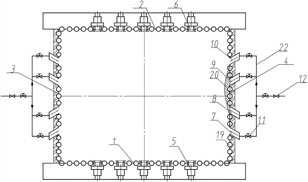
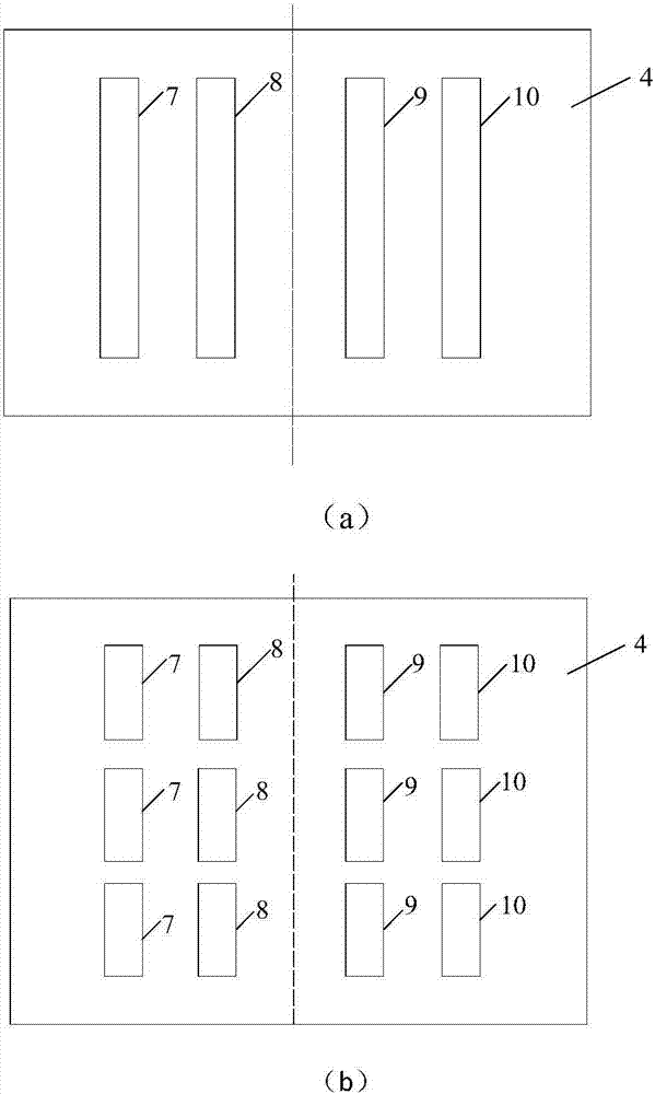
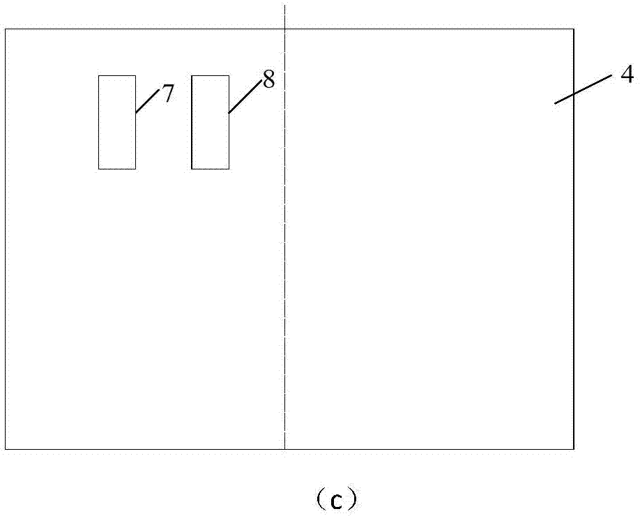
[0039] In this embodiment, a number of water-cooled walls 19 and their fins of the traditional boiler are cut off for the front and rear wall opposed combustion boilers, and the furnace wall is arranged on the right wall upstream of the high-temperature flame and flue gas pulverized coal flow in the water-cooled wall area of ​​the boiler. Be the slit type first tuyere 7 of certain angle. The slit-type first tuyere 7 forms a certain angle with the center line of the water-cooled wall 6, and the included angle is 30-45° or within an appropriate angle. The slit-type first tuyere 7 can be arranged in a whole section or in sections. see figure 2 (a), the entire arrangement is specifically that the height of the first tuyere 7 is the distance from the swirl burner at the lowest level of the boiler to the overfired air burner, see figure 2 (b), segmented arrangement is specifically to divide the first tuyeres 7 into several sections along the height direction, and the several sec...

Embodiment 2

[0045] see Figure 4 , for the counter-firing boiler, the right wall of the traditional boiler is divided into three sections: the right wall I section 13, the right wall II section 14 and the right wall III section 15, and the right wall II section 14 is prone to water-cooled wall In the area subject to high temperature corrosion, the distance from section 14 of the right wall II to the front wall 1 and the rear wall 2 is 1 / 3 of the depth of the furnace. Compared with traditional boilers, section II of the right wall 14 moves 150 mm to 200 mm outside the furnace, and forms a fifth tuyere 16 with section I of the right wall, section II of the right wall and section III of the right wall 15 The eighth tuyere 23 is formed therebetween, the fifth tuyere 16 is located upstream of the front wall burner 5 flame and flue gas flow, and the eighth tuyere 23 is located upstream of the rear wall burner 6 flame and flue gas flow. The heights of the fifth tuyere 16 and the eighth tuyere 2...


PUM


Abstract

Provided is a boiler water wall air film protection device. A plurality of tuyeres are arranged obliquely in an upstream boiler wall of high-temperature flame and flue gas coal dust airflow in the boiler water wall area and each tuyere communicate with an air flue arranged on the outer side of a hearth. Air is jetted into the hearth through the tuyeres, airflow forms an air curtain between the downstream portion of the flame and high-temperature flue gas flow and a water wall along the flue gas and the air curtain is towards the water wall under pushing of the flame and the high-temperature flue gas to form an air isolation layer, on the one hand, the action of the air curtain can push the wall-eroding coal dust airflow or flame to the center of the cross section of the hearth, so that erosive wear and corrosion to the water wall from the wall-eroding coal dust airflow or flame are avoided, and on the other hand, the air curtain is turned to the downstream water wall area under the action of the upstream high-temperature flame and flue gas, a layer of oxidizing atmosphere protection film is formed on the downstream water wall area, and the problem of high-temperature corrosion of the water wall is solved fundamentally.

Description

technical field [0001] The invention belongs to the field of boilers, and in particular relates to an air film protection device for boiler water walls. Background technique [0002] In recent years, with the implementation of the "Coal Power Energy Conservation and Emission Reduction Upgrading and Transformation Action Plan" [2014] No. 2093, coal-fired power plants have carried out a series of ultra-low emission transformations. To ensure that NO in flue gas x The emissions meet the emission standards and ease the operating pressure of the denitrification system. Most power plants have carried out low-nitrogen burner transformation or deep low-nitrogen burner transformation. However, under the low-nitrogen combustion mode, the main combustion area of ​​the boiler is in a weakly reducing atmosphere, and some water-cooled walls have a strong reducing atmosphere at the wall, and the H in the flue gas 2 The high content of S causes high temperature corrosion of the water-cool...

Claims


Application Information

Patent Timeline
Patent Type & Authority Applications(China)
IPC IPC(8): F23M5/08
CPCF23M5/085
Inventor 党黎军杨辉
Owner XIAN THERMAL POWER RES INST CO LTD
Learn More