Centrifugal casting machine of casting iron pan and centrifugal casting method thereof

A technology of centrifugal casting machine and cast iron pot, which is applied in the direction of casting mold, casting mold composition, casting molding equipment, etc. It can solve the problems that the surface cannot meet the production accuracy, the casting is not easy to be in place, and the productivity is hindered, so as to reduce the consumption of raw material metal and product quality. Production cost, improvement of surface quality, effect of reducing porosity

Inactive Publication Date: 2017-08-22
义乌市爱釜义自动化科技有限公司
View PDF7 Cites 9 Cited by
  • Summary
  • Abstract
  • Description
  • Claims
  • Application Information

AI Technical Summary

Problems solved by technology

[0003] However, in reality, due to the old technology, the development of productivity is hindered: the production cycle is long, the casting is not easy to be in place, the density is not enough, and the surface cannot meet the production precision, resulting in low yield rate, making people mistakenly think that cast iron pots are low-grade products. So many manufacturers choose other materials to make high-quality pots

Method used


Image

  • Centrifugal casting machine of casting iron pan and centrifugal casting method thereof

Examples


Embodiment 1

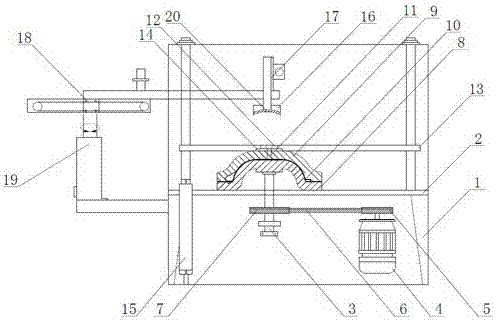
[0028] Embodiment 1: as figure 1 As shown, a cast iron pot centrifugal casting machine includes a frame 1, a lower support plate 2 is horizontally arranged on the frame 1, a rotating shaft 3 is vertically arranged on the lower support plate 2, and a rotating shaft 3 is arranged on the lower free end of the rotating shaft 3. The power drive mechanism further comprises a drive motor 4, a driving pulley 5, a drive belt 6 and a driven pulley 7, the drive pulley 5 is arranged on the motor shaft of the drive motor 4, and the driven pulley The pulley 7 is connected with the driving pulley 5 through the transmission belt 6 , and the driven pulley 7 is arranged on the lower free end of the rotating shaft 3 .

[0029] A lower mold 8 is arranged on the upper free end of the rotating shaft 3, and an upper mold 9 is arranged on the upper clutch of the lower mold 8, and a centrifugal chamber 10 is formed by fastening between the upper mold 9 and the lower mold 8, and the surface of the cent...

Embodiment 2

[0030] Embodiment 2: This casting machine also includes a manipulator discharge mechanism, and the manipulator discharge mechanism further includes an electromagnetic chuck 16, a lifting stroke cylinder 17, a translation stroke cylinder 18 and a rotating motor 19, and the electromagnetic chuck 16 is freely arranged on the lower mold 8 and outside the frame 1, the electromagnetic chuck 16 is installed on the lifting stroke cylinder 17, and the lifting stroke cylinder 17 is installed on the translation stroke cylinder 18, and the translation stroke cylinder 18 is installed on the rotary motor 19.

[0031] The lower end surface of the electromagnetic chuck 16 is a concave arc surface matched with the bottom of the pot, and several outwardly protruding heat-insulation flanges 20 are arranged on the concave arc surface.

[0032] A centrifugal casting method of a cast iron pot centrifugal casting machine, comprising the following steps:

[0033] (1) First, coat a layer of high-tempe...


PUM


Abstract

The invention discloses a centrifugal casting machine of a casting iron pan. The centrifugal casting machine comprises a rack. A lower bearing plate is horizontally arranged on the rack, a rotating shaft is vertically arranged on the lower bearing plate, and a power rotation-driving mechanism is arranged at a lower free end of the rotating shaft; a lower die is arranged at an upper free end of the rotating shaft, an upper die is arranged over the lower die in an on-off mode, and a centrifugal chamber is formed between the upper die and the lower die in a fastening mode; and a layer of high-temperature die coating layer is coated on the surface of the centrifugal chamber, a casting port communicating with the inner portion of the centrifugal chamber is formed in the upper die, the upper die is arranged on an upper bearing plate through a bearing, and the upper bearing plate is arranged on a lifting air cylinder. Centrifugal force enables specific pressure to increase sharply, and the functions that the density inside cast iron solution is increased, the crystal is compact, a fine grain layer is thickened, air holes inside the cast iron are decreased, and the surface quality is improved can be achieved easily; and the production period is shortened, the rate of finished products is improved, and the consumption of primary metal and the production cost of products are reduced.

Description

technical field [0001] The invention relates to the technical field of iron pan manufacture, and more specifically relates to a cast iron pan centrifugal casting machine and a centrifugal casting method thereof. Background technique [0002] At present, there are many casting techniques for cast iron pots, which can be roughly divided into two types: sand casting and die casting. Sand casting is to use clay bonded sand as molding material to produce castings. It is a process with a long history and the most widely used process. Die casting is a metal casting process characterized by the application of high pressure to molten metal using the cavity of a mold. Molds are usually machined from stronger alloys, a process somewhat similar to injection molding. [0003] However, in reality, due to the old technology, the development of productivity is hindered: the production cycle is long, the casting is not easy to be in place, the density is not enough, and the surface canno...

Claims


Application Information

Patent Timeline
Patent Type & Authority Applications(China)
IPC IPC(8): B22D13/00B22C3/00
CPCB22C3/00B22D13/00
Inventor 董永明
Owner 义乌市爱釜义自动化科技有限公司
Why Eureka
Try Eureka