Double-bed gasification unit and method
A technology for a gasification device and a gasification furnace, which is applied in the field of gasification, can solve the problem that the calorific value of gas is difficult to greatly increase, and achieve the effects of reducing the amount of pollutants, improving the quality of gas, and reducing damage
- Summary
- Abstract
- Description
- Claims
- Application Information
AI Technical Summary
Problems solved by technology
Method used
Image

Examples
Embodiment 1
[0046] In this example, the 10t / h circulating fluidized bed-moving bed double-bed low-rank coal gasification is taken as a specific example to illustrate this patent in detail.
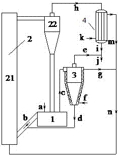
[0047] Wherein, the present embodiment uses air and water vapor as the gasification agent, and the device used in the present embodiment is as figure 2 As shown, it mainly includes: pyrolysis furnace 1, gasification furnace 2, pyrolysis gas condensation separator 3 and synthetic gas cooler 4.
[0048] The pyrolysis furnace 1 is a moving bed pyrolysis furnace, and its coal inlet is connected with the coal supply system; its semi-coke outlet is connected with the gasification furnace 21 of the gasification furnace 2 through the inclined leg of the return material; Its heat carrier inlet is connected with the material leg of the separator 22 of the gasifier 2 ; its pyrolysis gas outlet is connected with the pyrolysis gas inlet of the pyrolysis gas condensation separator 3 .
[0049] The gasification fu...
Embodiment 2
[0061] In this example, a 10 t / h fluidized bed-rotary bed twin-bed low-rank coal gasification in which the gasification agent is a mixture of air and steam is taken as a specific example. Wherein, in this embodiment, oxygen-enriched carbon dioxide gas and water vapor are used as gasification agents.
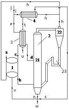
[0062] image 3 It is a schematic diagram of the twin-bed gasification device of the rotary bed pyrolysis furnace of the present invention, as image 3 As shown, the twin-bed gasification device in this embodiment mainly includes: a pyrolysis furnace 1 , a gasification furnace 2 , a pyrolysis gas condensation separator 3 and a synthetic gas cooler 4 .
[0063] Wherein, the pyrolysis furnace 1 is a rotary bed pyrolysis furnace, and its coal inlet is connected to the coal supply system; its semi-coke outlet is connected to the semi-coke inlet of the gasification furnace 21 of the gasifier 2; The gas outlet is connected to the gas pipe network system; the pyrolysis gas outlet is c...
PUM
| Property | Measurement | Unit |
|---|---|---|
| Calorific value | aaaaa | aaaaa |
Abstract
Description
Claims
Application Information
 - R&D
- Intellectual Property
- Life Sciences
- Materials
- Tech Scout
- Unparalleled Data Quality
- Higher Quality Content
- 60% Fewer Hallucinations
Browse by: Latest US Patents, China's latest patents, Technical Efficacy Thesaurus, Application Domain, Technology Topic, Popular Technical Reports.
© 2025 PatSnap. All rights reserved.Legal|Privacy policy|Modern Slavery Act Transparency Statement|Sitemap|About US| Contact US: help@patsnap.com