Low RCS wide-bandwidth angle-sweep phased array antenna based on strong mutual coupling effect

A phased array antenna, wide-angle scanning technology, applied in the field of antenna engineering, can solve problems such as unfavorable stealth design, narrow working bandwidth of microstrip antenna, inconvenient antenna design, etc., and achieve the effect of low RCS characteristics and significant RCS characteristics

Active Publication Date: 2017-08-22
UNIV OF ELECTRONICS SCI & TECH OF CHINA
View PDF6 Cites 26 Cited by
  • Summary
  • Abstract
  • Description
  • Claims
  • Application Information

AI Technical Summary

Problems solved by technology

However, based on this strong mutual coupling idea, there are also some shortcomings in the design of wide-bandwidth angular scanning phased arrays: the strong capacitively coupled dipole phased arrays of Munk et al. need to use more than two layers of microwave dielectric plates, and It is often required that the dielectric plate used as the wide-angle scanning impedance matching layer has a thickness proportional to the operating wavelength, so this implementation is not convenient for the design of conformal broadband phased array antennas on complex platform carriers
However, the microstrip antenna itself has a narrow operating bandwidth, which is difficult to meet the requirements of modern radar systems for wide-band operation, and it is also difficult to achieve wide-angle scanning
The Chinese patent "A 3.1-10.6GHz Vivaldi Ultra-Wideband Antenna" with the application number of 200620166938.1 can solve the requirement of broadband, but its section height is very high, and it is difficult to meet the design of conformal broadband phased array antenna on a complex platform carrier requirements, and its RCS is also high, which is not conducive to stealth design

Method used


Image

  • Low RCS wide-bandwidth angle-sweep phased array antenna based on strong mutual coupling effect
  • Low RCS wide-bandwidth angle-sweep phased array antenna based on strong mutual coupling effect
  • Low RCS wide-bandwidth angle-sweep phased array antenna based on strong mutual coupling effect

Examples


Embodiment 1

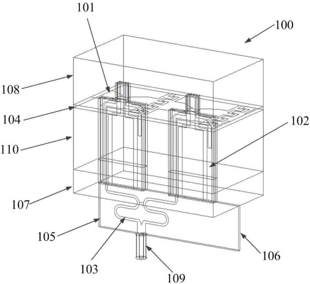
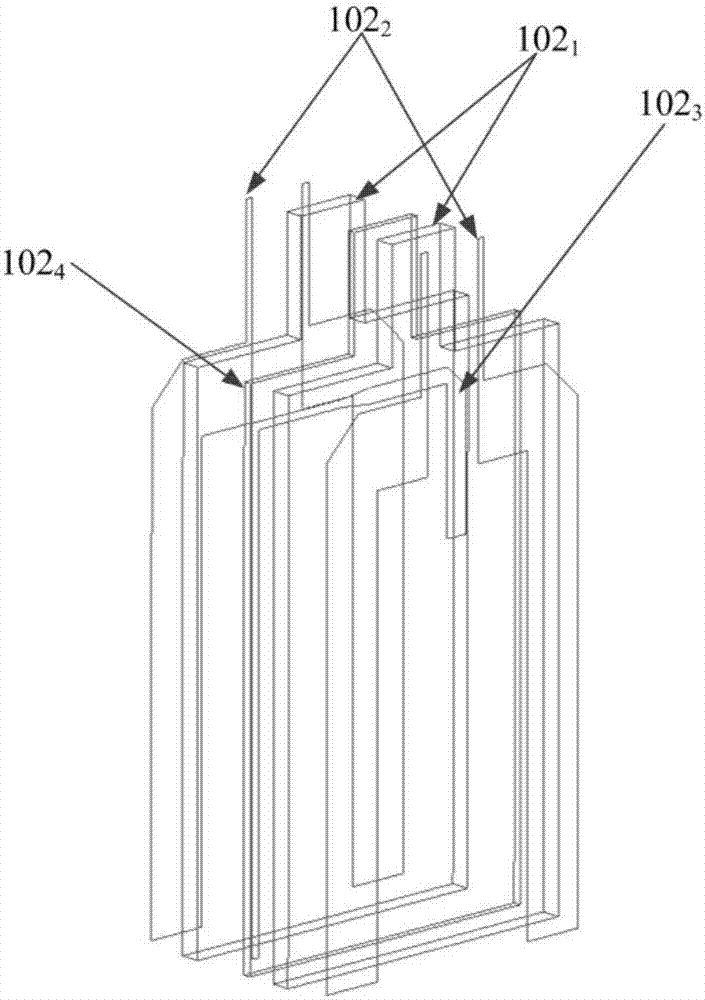
[0022] refer to figure 2 As shown in the unit structure, the low RCS wide bandwidth angular scanning phased array antenna 100 based on the strong mutual coupling effect of this embodiment is composed of interdigitated dipole patch units, and the periodic boundary conditions are used to simulate the present invention in an infinite array environment The simulation below. The antenna unit structure of the present invention is described as follows: printed on the dielectric layer 104 (thickness 10mil, relative permittivity ε r =2.2) on the interdigitated dipole unit 101, the two arms of the dipole unit 101 are fed through the multilayer impedance changing balun 102, one end of which is connected with the dipole unit, and one end is passed through the reflection level floor 107 and the feeder Intermediate layer stripline 102 of electric balun 102 3 It is connected with the power divider 103 and a microwave coaxial cable interface for inputting radio frequency energy to the feed...

Embodiment 2

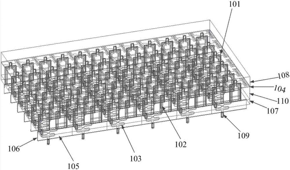
[0026] Specifically, each periodic unit is extended along the two-dimensional direction of the array to form figure 1 The 6×6 low RCS wide bandwidth angular scanning phased array antenna. Other structures and elements are the same as those described in Embodiment 1 in detail.

[0027] Figure 6 ~ Figure 8 The radiation pattern and scattering characteristic results of the second embodiment are given. which from Image 6 It can be seen that the array has stable beam pointing at different scanning angles, and the radiation characteristics during scanning are good; Figure 7 Shown is the single-station RCS comparison chart of the strong mutual coupling broadband phased array developed in Example 2 and the strong mutual coupling broadband phased array without impedance matching layer. It can be seen that the wide bandwidth angular scanning developed in Example 2 Phased array has good low scattering characteristics; Figure 8 Shown is a single-station RCS comparison diagram of...


PUM


Abstract

The invention discloses a low RCS wide-bandwidth angle-sweep phased array antenna based on a strong mutual coupling effect. The antenna comprises a radiation unit layer printed on a thin dielectric layer, and capacitive coupling between adjacent units is reinforced via an interdigital at the tail end of a dipole along the direction of a dipole arm in the radiation unit layer; and a multilayer impedance transformation Balun structure is used to feed the dipole. Thus, requirements of ultra wide band, wide-angle wave beam scanning and low RCS for the phased array antenna are all taken into consideration, and the low RCS wide-bandwidth angle-sweep phased array antenna is especially suitable for use in a new generation of hidden carrier platform.

Description

technical field [0001] The invention belongs to the technical field of antenna engineering, in particular to a wide bandwidth angular scanning phased array antenna system with low RCS characteristics. Based on the idea of ​​a strong mutual coupling effect, the invention proposes and designs a phased array antenna with characteristics such as ultra-wide operating frequency band, wide beam scanning angle, and low RCS, which is especially suitable for a new generation of stealth carrier platforms. Background technique [0002] As an indispensable and important part of the wireless system, the antenna is mainly used as a matching network connecting the RF input port and the free space to achieve the purpose of receiving and transmitting electromagnetic wave energy in a specific direction. Therefore, the performance of the antenna determines the performance of the entire wireless communication system. performance. Modern radar systems operate at increasing bandwidths due to the ...

Claims


Application Information

Patent Timeline
Patent Type & Authority Applications(China)
IPC IPC(8): H01Q1/38H01Q1/48H01Q1/50H01Q21/24
CPCH01Q1/38H01Q1/48H01Q1/50H01Q21/24
Inventor 杨仕文肖仕伟陈益凯王放刘坤宁屈世伟
Owner UNIV OF ELECTRONICS SCI & TECH OF CHINA
Why Eureka
Try Eureka