
Two-dimensional layered material-based device and preparation method therefor

A two-dimensional layered and device technology, which is applied in the manufacture of electrode components, the manufacture of discharge tubes/lamps, and parts of discharge tubes/lamps, etc., can solve problems such as poor electron emission characteristics and difficult application of micro-nano devices, and achieve The effect of simple device structure and improved field electron emission characteristics

Active Publication Date: 2017-09-01
SUN YAT SEN UNIV
View PDF8 Cites 4 Cited by
  • Summary
  • Abstract
  • Description
  • Claims
  • Application Information

AI Technical Summary

Problems solved by technology

[0004] The present invention aims to solve the problem in the prior art that the field electron emission characteristics of the plane end surface of the two-dimensional layered material are poor and difficult to be applied in micro-nano devices, and provides a method that can realize low-voltage field electron emission on the plane end surface of the two-dimensional layered material device

Method used


Image

  • Two-dimensional layered material-based device and preparation method therefor
  • Two-dimensional layered material-based device and preparation method therefor
  • Two-dimensional layered material-based device and preparation method therefor

Examples


Embodiment 1

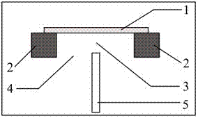
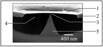
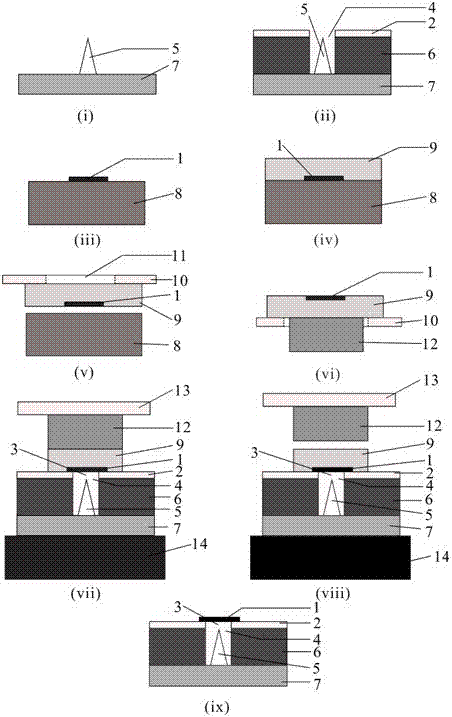
[0045] Such as figure 1 , figure 2 with image 3 (Ix) A device based on a two-dimensional layered material is shown, including electrode one 1 and electrode two 5; the electrode one is a two-dimensional layered material molybdenum disulfide; the electrode one is supported by an auxiliary component 2. , Placed in the air, the auxiliary component 2 is made of chromium material; the auxiliary component 2 is supported by the insulating layer 6; the electrode two 5 is a silicon cone, integrated with the silicon conductive substrate 7, and its top curvature radius It is 1-25 nm, which is specifically 10 nm in this embodiment; the area of ​​the suspended part of the electrode-1 is more than 3 times the area of ​​the tip of the electrode-2, which is specifically 10 in this embodiment. 4 Times; the width of the gap formed between the side of the electrode two 5 and the side of the auxiliary component 2 is 10-5000 nm, specifically 1000 nm in this embodiment; between the electrode one 1 an...

Embodiment 2

[0062] Except that the method for preparing the vacuum electronic device is different, other conditions are the same as in Example 1;

[0063] The vacuum electronic device is prepared by the following method:

[0064] S1. Using a micro-nano processing technology to prepare a silicon tip as electrode two 5 on a silicon conductive substrate 7; the height of the silicon tip is 100-1000nm, and the tip radius of curvature is 1-25nm; in this embodiment, the The height of the silicon cone is specifically 1000 nm, and the radius of curvature of the tip is specifically 10 nm;

[0065] S2. Prepare an insulating layer 6 on the silicon conductive substrate 7 outside the electrode two 5 by using a micro-nano processing technology, and prepare an auxiliary component 2 on the top of the insulating layer 6 to obtain a first combination; the upper surface of the auxiliary component 2 and the electrode The height difference of the top of the second 5 is 1-100 nm; in this embodiment, the height differ...


PUM

PropertyMeasurementUnit
thicknessaaaaaaaaaa
thicknessaaaaaaaaaa
heightaaaaaaaaaa

Abstract

The invention discloses a two-dimensional layered material-based device and a preparation method therefor. The device comprises an electrode I and an electrode II; the electrode I adopts a two-dimensional layered material; the electrode I is supported by an auxiliary part and placed in a suspension manner; a gap I is formed between the top ends of the electrode I and the electrode II; the area of the top end of the electrode II is smaller than the area of the suspension part of the electrode I; a gap II is formed between the side edge of the electrode II and the side edge of the auxiliary part; and when the device is in operation, a voltage is applied between the electrode I and the electrode II. By virtue of the device, low-voltage field-induced electron emission of the planar end plane of the two-dimensional layered material can be realized, and the device can be applied to a micro-nano vacuum triode or a photoelectric detector operated in low-voltage drive and low-vacuum conditions.

Description

Technical field [0001] The invention relates to the technical field of electronic and optoelectronic devices, and in particular to a device based on a two-dimensional layered material and a preparation method. Background technique [0002] Two-dimensional layered materials (such as graphene, molybdenum disulfide, tungsten diselenide, etc.) are a new type of electron field emission material. The thickness of a typical few-layer two-dimensional layered material (the number of atomic layers is 2-10) is less than 10nm, and its sharp edges have a strong electric field enhancement effect, which is conducive to obtaining low-voltage field electron emission. Therefore, most of the literatures that have been reported use the sharp edges of the two-dimensional layered materials to achieve low-voltage field electron emission, and they have been applied as an electron source. However, it is difficult to control the uniformity of the crystal structure and electronic properties of the two-dim...

Claims


Application Information

Patent Timeline
Patent Type & Authority Applications(China)
IPC IPC(8): H01J1/304H01J9/02H01J9/18B82Y40/00
CPCH01J1/3044H01J9/025H01J9/18B82Y40/00
Inventor 佘峻聪李炫廷邓少芝许宁生陈军
Owner SUN YAT SEN UNIV
Learn More