Thermal power generating unit control method and system based on condensate throttling

A technology for condensate water throttling and thermal power units, which is applied in the direction of water supply control, supplementary water supply, preheating, etc., and can solve problems such as low efficiency, reduced service life of equipment, and unit load overload

Inactive Publication Date: 2017-09-08
HANGZHOU E ENERGY ELECTRIC POWER TECH +3
View PDF3 Cites 6 Cited by
  • Summary
  • Abstract
  • Description
  • Claims
  • Application Information

AI Technical Summary

Problems solved by technology

[0004] The existing condensate water throttling technology for unit load control has low efficiency and untimely control of the interception water level
In addition, the control strategy is not perfect enough to overload the unit load and reduce the service life of the equipment

Method used


Image

  • Thermal power generating unit control method and system based on condensate throttling
  • Thermal power generating unit control method and system based on condensate throttling
  • Thermal power generating unit control method and system based on condensate throttling

Examples


Embodiment 1

[0064] This embodiment is a thermal power unit control method based on improved condensate throttling, including the following steps:

[0065] Step 1, optimization control strategy analysis

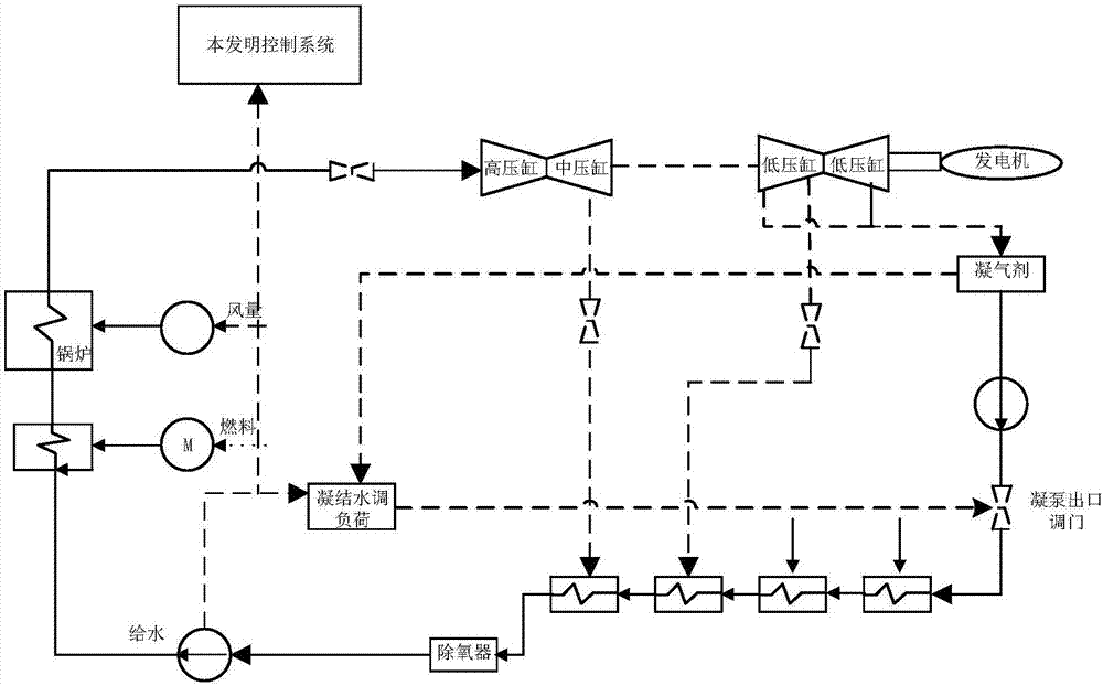
[0066] Step 11 is based on the water level changes of the deaerator and condenser, and adjusts the water level change according to the opening of the water supply regulating valve.

[0067] Step12 Improve the low-pressure heater drainage control system to realize the stable control of the low-pressure heater in the condensate throttling control system and improve the stability of the system.

[0068] Step13 Optimize the control of the load command of the unit to realize the opening and closing of the throttle valve and the control of the caliber flow freely, so as to ensure the safe operation of the unit.

[0069] Step 2, according to the law of conservation of mass and energy, establish the thermal economic state equation

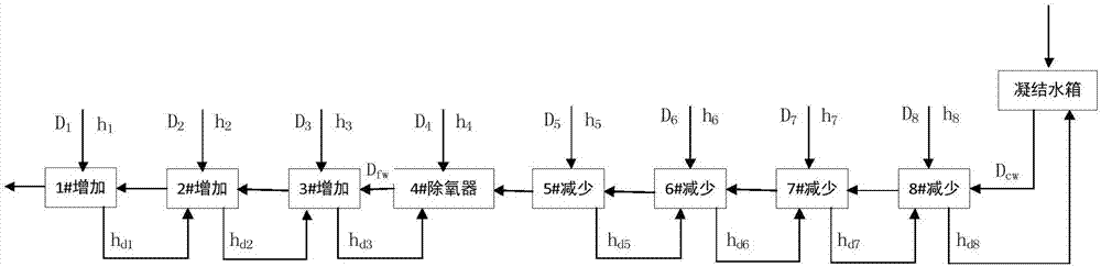
[0070] Step21 soda distribution equation:

[0071] [A][D i ]...

Embodiment 2

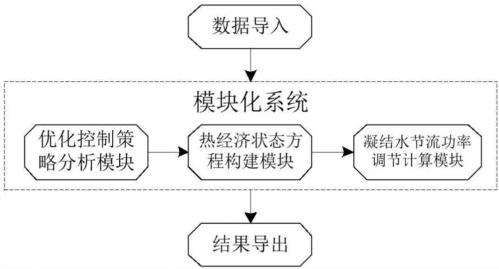
[0108] This embodiment is a thermal power unit control system based on improved condensate throttling, including:

[0109] Optimal control strategy analysis module: Based on the water level changes of the deaerator and condenser, the water level change is adjusted according to the opening of the water supply regulating valve; the low-pressure heater drain control system is improved, and the low-pressure heater is throttled in the condensate The smooth control in the control system improves the stability of the system; optimizes the control of the load command of the unit, realizes the opening and closing of the throttle valve port and the flow control of the caliber freely, and ensures the safe operation of the unit;

[0110] Thermal economic state equation building block: used to construct the steam-water distribution equation, the system power output power equation, and the system power input energy equation;

[0111] Condensate throttling power adjustment calculation module...


PUM


Abstract

The invention discloses a thermal power generating unit control method and system based on condensate throttling. In real life, a traditional thermal power generating unit control system has control delay and combustion inertia and other prominent problems. The variable load control strategy of complete sliding pressure and condensate flow regulation is adopted in the load adjusting method based on condensate throttling, rapid changes of the condensate flow within short time are controlled, within the water level adjusting range of a deaerator and a condenser, the size of a valve port is adjusted to increase or decrease the condensate flow value, the steam exhaust amount adjustment of a steam turbine in a low-pressure heater and the deaerator is achieved, and loads of one part of unit can be obtained or released within short time. The use efficiency of a traditional condensate control system is improved, in the energy-saving management control of a thermoelectric unit power station, the large energy-saving can be achieved, economic benefits are generated, and the actual application value is achieved.

Description

technical field [0001] The invention relates to the technical field of electromechanical intelligent control, in particular to a thermal power unit control method and system based on condensed water throttling. Background technique [0002] Usually, the frequency conversion capability is a necessary capability for generating sets to be connected to the grid. The fast and stable grid frequency and high-quality electrification technology can meet the requirements of the hybrid grid. In order to realize and meet the requirements of electrification technology, the energy saving and performance control of thermal power generation units in traditional thermal power plants mainly rely on controlling the fuel in and out of the unit to achieve the purpose of controlling the unit load. In reality, it is found that the traditional unit control system has outstanding problems such as control delay and combustion inertia. Therefore, new management and control technologies have to be co...

Claims


Application Information

Patent Timeline
Patent Type & Authority Applications(China)
IPC IPC(8): F22D5/26F22D11/06
CPCF22D5/26F22D11/06
Inventor 胡建根张国立赵琦罗志浩陈波张明樊印龙吴春潮左东明熊建国
Owner HANGZHOU E ENERGY ELECTRIC POWER TECH
Why Eureka
Try Eureka