
Field-oriented control driving system and control method of brushless motor

A technology of brushless motor and magnetic field orientation, applied in control system, vector control system, motor generator control, etc., can solve the problems of output torque, limited output current, high cost of exoskeleton robot, driving effect cannot meet high-end requirements, etc. , to achieve the effect of high position control accuracy

Inactive Publication Date: 2017-09-08
深圳市极拓医疗科技有限公司
View PDF6 Cites 9 Cited by
  • Summary
  • Abstract
  • Description
  • Claims
  • Application Information

AI Technical Summary

Problems solved by technology

[0004] 1. Grating encoders are generally used as motor rotor position detection sensors, which are very expensive and increase the production cost of the product
[0005] 2. The operating frequency of the main control MCU is mostly less than 90MHz, which cannot help high-end needs
[0006] 3. The maximum continuous working current allowed by the field-oriented controller has various gradients, but the cost of high current is very high, and the high load capacity of exoskeleton robots requires the support of large currents, which makes the overall cost of exoskeleton robots high. The price is also high, which is not conducive to ordinary people's use
[0007] In addition, most of the mature commercial controllers currently on the market still use RS485 communication interface, and the data transmission rate is low; most of the driving circuits do not have MOSFET bridge pre-drivers, and the driving effect cannot meet high-end requirements; the output torque and output current are limited, which cannot meet High torque and high current application requirements

Method used


Image

  • Field-oriented control driving system and control method of brushless motor
  • Field-oriented control driving system and control method of brushless motor
  • Field-oriented control driving system and control method of brushless motor

Examples


Embodiment Construction

[0061] In order to make the object, technical solution and advantages of the present invention more clear, the present invention will be further described in detail below in conjunction with the accompanying drawings and embodiments. It should be understood that the specific embodiments described here are only used to explain the present invention, not to limit the present invention. On the contrary, the purpose of providing these embodiments is to make the disclosure of the present invention more thorough and comprehensive.

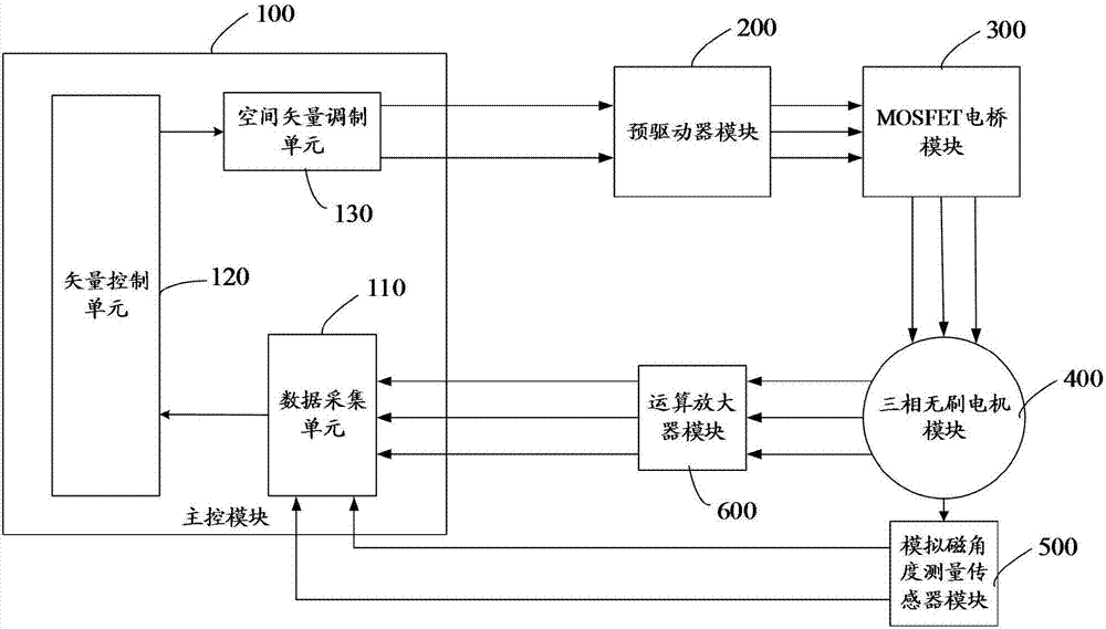
[0062] figure 1 It is a block diagram of a brushless motor field oriented control driving system of an embodiment. The brushless motor field-oriented control system includes a main control module 100 with a built-in field-oriented control algorithm, a pre-driver module 200, a MOSFET bridge module 300, a three-phase brushless motor module 400, an analog magnetic angle measurement sensor module 500, and an operational amplifier. Module 600.

[0063] Whe...


PUM


Abstract

The invention relates to a field-oriented control driving system and control method of a brushless motor. The field-oriented control driving system comprises a master control module, a pre-driver module, a metal-oxide-semiconductor field-effect transistor (MOSFET) bridge module and an analogue magnetic angle measurement sensor module, wherein the analogue magnetic angle measurement sensor module is used for measuring an angular position or a brushless motor rotor in real time and feeding the angular position back to the master control module, the master control module is used for adjusting three paths of complementary pulse width modulation (PWM) waveforms according to angular position information and three-phase current information, and the pre-driver module is used for generating a corresponding waveform to drive the MOSFET bridge module so as to drive running of a three-phase brushless motor. The field-oriented control driving system and control method of the brushless motor employs an analogue magnetic angle measurement sensor and a field-oriented control algorithm, the angle of the brushless motor rotor can be rapidly and accurately measured by the sensor, the position of the motor rotor can be accurately controlled, enough large torque can be output, and the application demand of a robot is satisfied.

Description

technical field [0001] The invention relates to the technical field of brushless motor control and drive, in particular to a high-performance brushless motor field-oriented control drive circuit and control method that can be used for exoskeleton robots. Background technique [0002] At present, most of the commercial brushless motor drive circuits on the domestic market are based on the six-step control method of the Hall sensor rather than the Field Oriented Control (FOC) method. However, the six-step control method based on the Hall sensor, due to the limitation of the detection mechanism of the Hall sensor, makes the position control accuracy of the brushless motor operation low, the highest position control accuracy is usually less than 5 degrees, and the output torque effect is poor, and the power consumption is low. big. However, in some application fields of brushless motors, such as the drive control of exoskeleton robots, high control accuracy is required, and the...

Claims


Application Information

Patent Timeline
IPC IPC(8): H02P21/18H02P21/00
CPCH02P21/00H02P21/18
Inventor 万超王亮东人梁哲
Owner 深圳市极拓医疗科技有限公司
Learn More