
Manufacturing method of cable for high power transmission equipment and cable

A technology of power transmission and manufacturing method, applied in cable/conductor manufacturing, power cables with shielding/conducting layers, coaxial cables, etc., can solve problems such as poor flexibility, deformation, and failure to meet installation and laying requirements in small spaces

Inactive Publication Date: 2017-09-12
JIANGSUSNGSHANG CABLE GROUP
View PDF0 Cites 12 Cited by
  • Summary
  • Abstract
  • Description
  • Claims
  • Application Information

AI Technical Summary

Problems solved by technology

[0004] When transmitting high electric energy, overload heating will occur, which will reduce the service life of the cable. In severe cases, the cable will be burned to cause fire and property loss; the weight is large, the outer diameter is large, the flexibility is poor, and the bending radius is large, which does not meet the requirements for installation and laying in small spaces; Difficult to apply to -60 ℃ low temperature extreme cold environment;
[0005] The cable structure design and manufacturing method are unreasonable. When transmitting high power, the cable conductor is prone to deformation under the strong electromagnetic force of the coaxial cable itself. In severe cases, the extrusion damages the insulation, causing the system to malfunction and cannot operate normally.

Method used


Image

  • Manufacturing method of cable for high power transmission equipment and cable
  • Manufacturing method of cable for high power transmission equipment and cable

Examples


example 1

[0177] In the step 3)

[0178] Extrusion: the body temperature is controlled at 5°C;

[0179] Vulcanization vapor pressure, temperature and time are 0.75MPa, 165°C, 18min;

[0180] Cooling water level: water level setting 16%

[0181] In the step 7)

[0182] Extrusion: the body temperature is controlled at 15°C;

[0183] Vulcanization vapor pressure, temperature and time are 0.80MPa, 170°C, 22min;

[0184] Cooling water level: water level setting 18%

[0185] In the step 8)

[0186] Extrusion: Zone 1 160°C, Zone 2 165°C, Zone 3 170°C, Zone 4 175°C, Zone 5 175°C, Zone 6 180°C, Zone 1 180°C, Zone 2 180°C, Zone 3 Zone 180°C, 180°C in the fourth zone of the machine head;

[0187] Cooling: The temperature range of the cooling water in the first zone is [50, 60°C], and the temperature range of the cooling water in the second zone is room temperature.

example 2

[0189] In the step 3)

[0190] Extrusion: the body temperature is controlled at 15°C;

[0191] Vulcanization steam pressure, temperature and time are 0.80MPa, 170°C, 16min;

[0192] Cooling water level: water level setting 18%

[0193] In the step 7)

[0194] Extrusion: the body temperature is controlled at 15°C;

[0195] Vulcanization vapor pressure, temperature and time are 0.85MPa, 175°C, 20min;

[0196] Cooling water level: water level setting 18%

[0197] In the step 8)

[0198] Extrusion: Zone 1 170°C, Zone 2 175°C, Zone 3 180°C, Zone 4 185°C, Zone 5 185°C, Zone 6 190°C, Zone 1 190°C, Zone 2 190°C, Zone 3 Zone 190°C, 190°C in the fourth zone of the machine head;

[0199] Cooling: The temperature range of the cooling water in the first zone is [40, 43°C], and the temperature range of the cooling water in the second zone is room temperature.

example 3

[0201] In the step 3)

[0202] Extrusion: the body temperature is controlled at 25°C;

[0203] Vulcanization vapor pressure, temperature and time are 0.85MPa, 175°C, 14min;

[0204] Cooling water level: water level setting 20%

[0205] In the step 7)

[0206] Extrusion: the body temperature is controlled at 15°C;

[0207] Vulcanization steam pressure, temperature and time are 0.90MPa, 180℃, 18min;

[0208] Cooling water level: water level setting 17%

[0209] In the step 8)

[0210] Extrusion: Zone 1 180℃, Zone 2 185℃, Zone 3 190℃, Zone 4 195℃, Zone 5 195℃, Zone 6 200℃, Zone 1 200℃, Zone 2 200℃, Zone 3 Zone 200°C, head four zone 200°C;

[0211] Cooling: The temperature range of the cooling water in the first zone is (43, 50°C), and the temperature range of the cooling water in the second zone is room temperature.

[0212] Use of this cable: The cable is laid in high power transmission equipment in a small space.

[0213] After testing, the performance of this cable is...


PUM

PropertyMeasurementUnit
Wire diameteraaaaaaaaaa
The average thicknessaaaaaaaaaa

Abstract

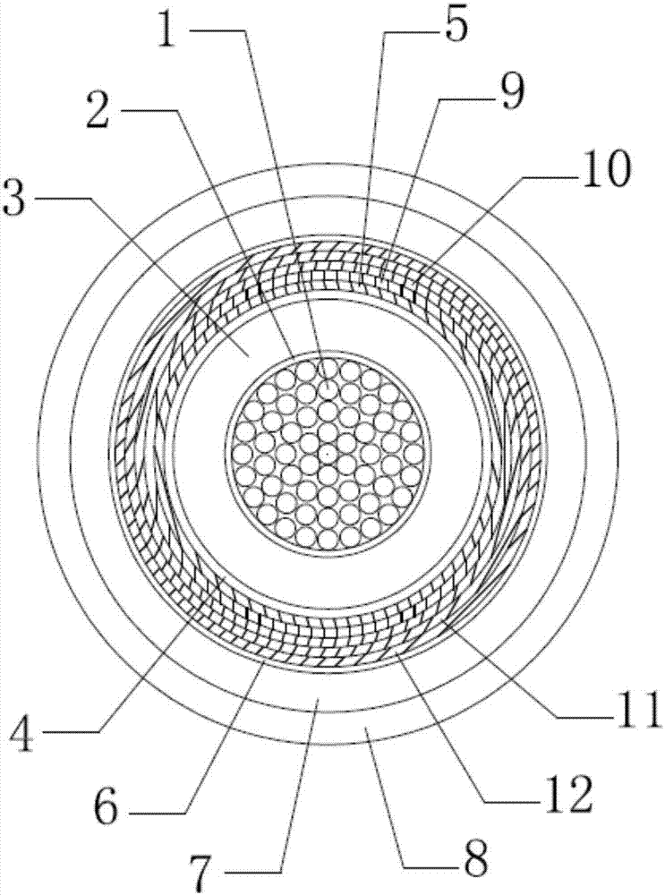
A cable for high power transmission equipment, its structure from inside to outside is: inner conductor, first semiconductive wrapping shielding layer, inner conductor insulation, second semiconducting wrapping shielding layer, outer conductor, wrapping layer, Outer conductor insulation and outer sheath. The insulating layer of the inner conductor is made of silicon rubber; the outer conductor is braided with one or more layers of tinned copper wire; the insulating layer of the outer conductor is made of silicon rubber; the outer sheath layer is made of polyurethane. The manufacturing method of the cable comprises: 1) manufacturing the inner conductor; 2) manufacturing the first semiconductive wrapping shielding layer; 3) manufacturing the inner conductor insulating layer; 4) manufacturing the second semiconductive wrapping shielding layer; 5) manufacturing 6) manufacturing the wrapping layer; 7) manufacturing the insulating layer of the outer conductor; 8) manufacturing the outer sheath layer. In each step, a specific process method is adopted, so that the electrical and mechanical properties of the cable prepared by this method can meet or exceed the detection requirements, so that the cable for high-power transmission equipment can transmit high power safely and reliably, and has the advantages of light weight. , miniaturization, low temperature resistance, good flexibility, small bending radius and other excellent performances, suitable for high electric energy technical equipment.

Description

technical field [0001] The technical solution relates to the technical field of cables, in particular to cables for high electric energy transmission systems and a manufacturing method thereof. Background technique [0002] Most power cables have a two-core structure. Due to their own characteristics, they are suitable for power transmission in rail transit and other fields, and there are many inconveniences. In general, coaxial power cables can be used instead. [0003] The coaxial power cables in the prior art have the following deficiencies: [0004] When transmitting high electric energy, overload heating will occur, which will reduce the service life of the cable. In severe cases, the cable will be burned to cause fire and property loss; the weight is large, the outer diameter is large, the flexibility is poor, and the bending radius is large, which does not meet the requirements for installation and laying in small spaces; Difficult to apply to -60 ℃ low temperature ...

Claims


Application Information

Patent Timeline
IPC IPC(8): H01B7/02H01B7/18H01B9/02H01B9/04H01B13/02H01B13/26H01B13/06H01B13/14H01B7/04
CPCH01B7/0216H01B7/0275H01B7/04H01B7/18H01B7/186H01B9/02H01B9/04H01B13/02H01B13/06H01B13/14H01B13/26
Inventor 周大亮李斌梁福才沙伟宋鹏戴菁伟裴文
Owner JIANGSUSNGSHANG CABLE GROUP
Learn More