Compressed air dryer

A compressed air and dryer technology, applied in gas treatment, chemical instruments and methods, membrane technology, etc., can solve problems such as prone to equipment failure, increased perforation, poor anti-interference, etc., to achieve improved water exchange efficiency and no easy loss Parts and effects of heat exchange efficiency improvement

Active Publication Date: 2017-10-03
刘友葵
View PDF6 Cites 2 Cited by
  • Summary
  • Abstract
  • Description
  • Claims
  • Application Information

AI Technical Summary

Problems solved by technology

[0008] However, the problems in the above-mentioned patents are that the structure is complex and prone to equipment failure, which is manifested in three aspects. The first aspect is that the heat exchange cycle is carried out between the two adsorption towers through the fan and the heater, and the fan or the heater is out of order. , the whole system needs to be shut down for maintenance; secondly, heat exchange tubes are installed inside the two adsorption towers, which takes up too much space inside the adsorption towers, so that the amount of adsorbents that can be accommodated is reduced, and more importantly, complex heat transfer Pipe, working for a long time in the working environment of alternating cold and hot, the possibility of perforation will increase greatly after a long time. Orderly work, poor anti-interference, frequent malfunctions, and "crash" phenomena; fourth, there is no online measurement and control of the moisture in the dried compressed air, and the quality of the compressed air supplied to users is not guaranteed

Method used


Image

  • Compressed air dryer

Examples


Embodiment Construction

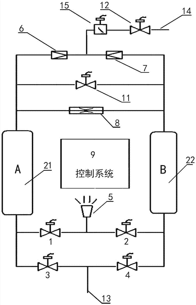
[0022] figure 1 It is a three-dimensional schematic diagram of a compressed air dryer, including two adsorption tanks A and B filled with adsorbents arranged in parallel, and the lower parts of the adsorption tanks A and B are connected in parallel through two intake valves and two dehumidification valves , the air inlet is set between the two intake valves 3 and 4, and the muffler is set between the two dehumidification valves 1 and 2; The check valves opposite to the output end are connected, and the outlet valve is connected between the two check valves 6 and 7, and the outlet valve is connected to the moisture detector; the control system is connected with the inlet valve, the dehumidification valve, the pilot valve, the outlet valve and The moisture detector is electrically connected.

[0023] The adsorbent is activated alumina particles, adsorption tank A and adsorption tank B are made of steel, various connecting pipes are made of PPR material, and various valves are m...


PUM


Abstract

The invention relates to a compressed air dryer in the field of air dehumidifying technological equipment. The compressed air dryer comprises an adsorption tank A and an adsorption tank B which are arranged in parallel and are filled with adsorbents; the lower parts of the adsorption tank A and the adsorption tank B are connected in parallel via two air inlet valves and two humidity discharging valves; an air inlet is formed between the two air inlet valves; a silencer is arranged between the two humidity discharging valves; the upper parts of the adsorption tank A and the adsorption tank B are connected via a throttle valve, a pilot valve and two check valves; the output ends of the two check valves are opposite to each other; a moisture detection instrument and an air outlet valve are connected between the check valves. The compressed air dryer realizes two functions of drying and dehydration regeneration, realizes water closed ring automatic control, and is simple and reliable in structure; a control system adopts a PLC (programmable logic controller) and realizes accurate control, the adsorbents are active aluminum oxide particles, the adsorption force is strong, the adsorbents are in a fluid state in the adsorption tank A and the adsorption tank B, water exchange and heat exchange are conducted, the exchange efficiency is doubled, and the compressed air dryer is worthy of wide popularization and application.

Description

technical field [0001] The invention relates to the field of air dehumidification technical equipment, in particular to a compressed air dryer. Background technique [0002] The production and power of many industries need to use dry compressed air, such as vehicle painting in automobile production companies, wig production, industrial assembly lines, equipment and other power supplies. The use of dry compressed air can ensure the quality and quantity of the product and prolong the service life of the equipment. [0003] As we all know, there are two kinds of gas drying methods: adsorption method and cooling method. The adsorption method saves energy, and its drying dew point can be as low as -40°C; the cooling method consumes a lot of energy, and its dew point is only +3°C. With the same output and quality, if the cooling method consumes 1,000 yuan a day, the adsorption method only consumes 10 yuan a day, which is a hundred times the difference. Therefore, adsorption dry...

Claims


Application Information

Patent Timeline
Patent Type & Authority Applications(China)
IPC IPC(8): B01D53/12B01D53/26
CPCB01D53/12B01D53/261B01D2259/40086B01D2253/10B01D2253/104B01D2253/106
Inventor 刘友葵余志炜李瑞群张卓勋刘剑君张茗丽刘振辉
Owner 刘友葵
Why Eureka
Try Eureka