Active clamping flyback switching power supply circuit

A switching power supply circuit, switching power supply technology, applied in the direction of high-efficiency power electronic conversion, electrical components, adjusting electric variables, etc., can solve the problems of large electromagnetic interference, loss, no output, etc., achieve zero voltage turn-on, improve conversion efficiency, Realize the effect of energy recovery

Active Publication Date: 2017-10-20
MORNSUN GUANGZHOU SCI & TECH
View PDF6 Cites 6 Cited by
  • Summary
  • Abstract
  • Description
  • Claims
  • Application Information

AI Technical Summary

Problems solved by technology

[0004] The inductance of the primary winding is also low, and it often happens that the calculated number of turns cannot be tiled from the left to the right of the wire slot that is full of the skeleton. When the working voltage is high, the sandwich series winding method can be used. At low working voltage Downside, it is forced to adopt the sandwich parallel winding method. Since the two primary windings are not on the same layer, there is a leakage inductance between the two primary windings. This leakage inductance will cause losses, thereby reducing the efficiency of the switching power supply. , the loss problem caused by the leakage inductance between the two parallel primary windings: this will exist during excitation and demagnetization; Which of the side windings is wound in parallel, only two tertiary windings can be used, which are respectively wound in parallel with the two parallel primary windings, and then connected in parallel to form a "third winding". The process is complicated, and the third winding composed of two parallel windings Windings also induce unequal voltages, causing losses and greater electromagnetic interference
[0005] In fact, for the common demagnetization of the third winding, the advantage is lossless demagnetization and high efficiency, but the selection of the wire diameter of the third winding is also a problem: the selection is relatively thin, and it is troublesome to wind in parallel with the primary winding, and it is easy to The thin wire is broken; if the wire diameter is selected to be the same as that of the primary winding, the cost will be high
But in these two schemes, Figure 1-2 This demagnetization method has strict requirements on the leakage inductance, otherwise, the excitation energy may be directly returned to the DC power supply U by D1 DC , does not appear in the secondary winding N S In the middle, there is no current in the secondary side D2, so that the output voltage is low or there is no output; and it is required that the reflected voltage generated when D2 is turned on cannot be greater than the DC power supply U DC , and if the duty cycle cannot be greater than 0.5, the power density cannot be further improved
for Figure 1-3 , the degaussing circuit itself is a more classic topology, the duty cycle can be greater than 0.5, and the energy of the leakage inductance has not been recycled

Method used


Image

  • Active clamping flyback switching power supply circuit
  • Active clamping flyback switching power supply circuit
  • Active clamping flyback switching power supply circuit

Examples


no. 1 example

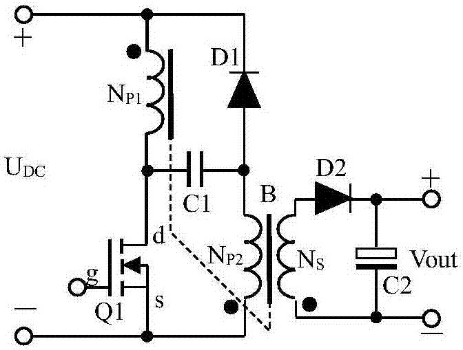
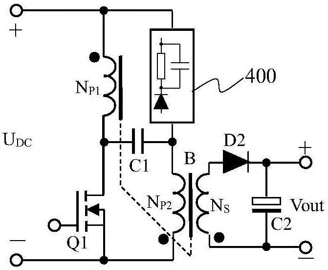
[0034] diagram 2-1 with Figure 2-2 It shows the principle diagram of the active clamp flyback switching power supply circuit of the first embodiment of the present invention, including a transformer B, a first N-channel field effect transistor Q1, a first capacitor C1, a second capacitor C2, a first Diode D2, clamping network 400, transformer B including first primary winding N P1 , the second primary winding N P2 and the secondary winding N S , the clamping network 400 includes at least an anode and a cathode, and the secondary winding N S The opposite end is connected to the anode of the first diode D2, and the cathode of the first diode D2 is connected to one end of the second capacitor C2 to form a positive output, which is the + end of Vout in the figure, and the secondary winding N S The end with the same name is connected to the other end of the second capacitor C2 to form a negative output, which is the - end of Vout in the figure; input DC power U DC (hereinaft...

no. 2 example

[0067] The present invention also provides an equivalent solution to the above-mentioned first embodiment, corresponding to solution 2, see Figure 3-1 , Figure 3-2 , an active clamping flyback switching power supply circuit, comprising a transformer B, a first N-channel FET Q1, a first capacitor C1, a second capacitor C2, a first diode D2, and a clamping network 400, Transformer B includes the first primary winding N P1 , the second primary winding N P2 and the secondary winding N S , the clamping network 400 includes at least an anode and a cathode, and the secondary winding N S The opposite end is connected to the anode of the first diode D2, and the cathode of the first diode D2 is connected to one end of the second capacitor C2 to form a positive output, which is the + end of Vout in the figure, and the secondary winding N S The end with the same name is connected to the other end of the second capacitor C2, and forms an output negative, which is the - end of Vout in...


PUM


Abstract

An active clamping flyback switching power supply circuit is provided. Based on a LCL flyback converter, the NP1 corresponding terminal in a transformer B is connected with a power supply, a second primary winding NP2 corresponding terminal is connected to ground, the NP1 and the NP2 are both wound by two wires. One end of a capacitor C1 is connected to the NP1 non-corresponding terminal, and the other end of the capacitor C1 is connected to the NP2 corresponding terminal. The NP2 corresponding terminal is connected to the power supply via a field-effect transistor Q2 and a clamping network 400 connected with a C3 in series. Thus, when the Q1 is in saturated conduction, the NP1 and the NP2 are both excited. When the Q1 is switched off, a secondary side outputs energy, a primary side presents a state that a voltage source is connected in series with leakage inductance, the Q2 is switched on, the C3 and leakage inductance resonate so as to switch on the Q1 at zero voltage. In a light load state, the Q2 is switched on at intervals of a few cycles during which the voltage of the C3 increases step by step. When the Q2 is switched on, the C3 and leakage inductance resonate so as to switch on the Q1 at zero voltage, and further reduce the power consumption of driving the Q2 at the light load state, and achieve a duty cycle greater than 0.5, energy recovery of a demagnetization circuit, especially at the light load state, the conversion efficiency is improved.

Description

technical field [0001] The invention relates to the field of switching power supplies, in particular to a flyback switching power supply using active clamping. Background technique [0002] Switching power supplies are widely used. For occasions where the input power is below 75W and the power factor (PF, Power Factor, also known as power factor) is not required, the flyback switching power supply has attractive advantages: the circuit topology is simple , wide input voltage range. Due to the small number of components, the reliability is relatively high, so it is widely used. For convenience, many documents are also called flyback switching power supply, flyback power supply, and flyback converter. Japan and Taiwan are also called flyback converters, flyback switching power supplies, and flyback power supplies. Common topologies for AC / DC converters such as Picture 1-1 , the prototype of the figure comes from page 60 of "Switching Power Converter Topology and Design" wri...

Claims


Application Information

Patent Timeline
Patent Type & Authority Applications(China)
IPC IPC(8): H02M3/335
CPCH02M3/33569H02M1/0058H02M3/01Y02B70/10
Inventor 王保均
Owner MORNSUN GUANGZHOU SCI & TECH
Why Eureka
Try Eureka