
Heat exchange system of demethanizer and heat exchange method

A technology of demethanizer and heat exchange system, which is applied in the field of demethanizer heat exchange system and heat exchange, and can solve the problems such as difficult to change refrigerant level, low local temperature of cracked gas, difficult temperature of cracked gas, etc.

Active Publication Date: 2017-10-24
SINOPEC ENG +1
View PDF3 Cites 4 Cited by
  • Summary
  • Abstract
  • Description
  • Claims
  • Application Information

AI Technical Summary

Problems solved by technology

[0004] The refrigerant of the demethanizer is provided by the refrigeration system. Due to the lower boiling point of hydrogen, it is more difficult to liquefy. To condense more hydrogen, a cooler grade of refrigerant is required. When the refrigerant ratio remains unchanged It is difficult to change the level of refrigerant under low conditions. As a result, the heat transfer temperature difference of the demethanizer condenser is too low (less than 2.5°C), and the loss rate of ethylene increases, that is, "the cold can't cool down"
Only by increasing the outlet pressure of the pyrolysis gas compressor to increase the operating pressure of the demethanizer can the loss of ethylene be controlled, but this will greatly increase the power consumption of the compressor, resulting in an increase in the energy consumption of the entire system
On the other hand, the recovery of the cooling capacity of the tail gas in the cold phase may be locally unbalanced, causing the local temperature of the cracked gas to be too low, that is, "the one that should not be cold is cooled down", making it difficult to control the temperature of the cracked gas and affecting the temperature of the tower. Gas-liquid load distribution, resulting in loss of tray efficiency
Insufficient recovery of tail gas cooling capacity, entering the follow-up process, the cooling capacity temperature level does not match the process flow, which causes waste and is difficult to control

Method used


Image

  • Heat exchange system of demethanizer and heat exchange method
  • Heat exchange system of demethanizer and heat exchange method
  • Heat exchange system of demethanizer and heat exchange method

Examples


Embodiment 1

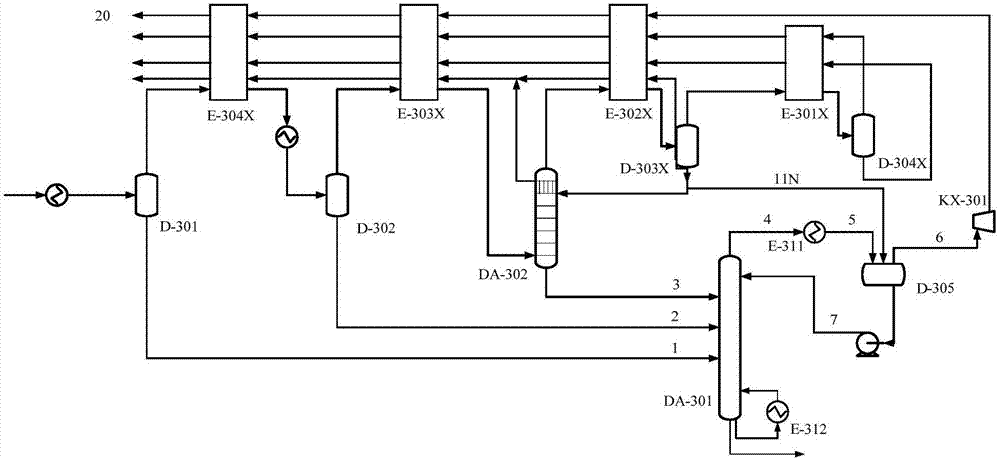
[0058] like figure 1 As shown, a demethanizer heat exchange system.

[0059] Including: demethanizer DA-301, demethanizer condenser E-311, demethanizer reflux tank D-305, 1# hydromethane separation tank D-303X, 2# hydromethane separation tank D-304X and cold box, The cold box includes 1# cold box E-301X, 2# cold box E-302X, 3# cold box E-303X and 4# cold box E-304X connected in sequence, and the top outlet of the demethanizer DA-301 is connected to the demethanizer The condenser E-311 is connected to the demethanizer reflux tank D-305, the gas phase outlet of the demethanizer reflux tank D-305 is connected to 2# cold box E-302X, and the liquid phase outlet of the demethanizer reflux tank D-305 is connected to the demethanizer The upper part of DA-301, 2# cold box E-302X is connected to 1# hydrogen methane separation tank D-303X, 2# hydrogen methane separation tank D-304X is connected to 1# cold box E-301X, 1# hydrogen methane separation tank D-303X One branch of the bottom o...

Embodiment 2

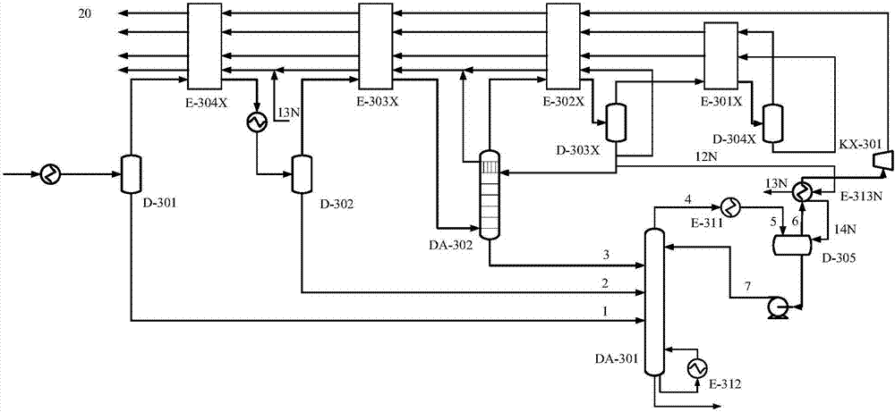
[0063] like figure 2 as shown,

[0064] A demethanizer heat exchange system.

[0065] Including: demethanizer DA-301, demethanizer condenser E-311, demethanizer reflux tank D-305, 1# hydromethane separation tank D-303X, 2# hydromethane separation tank D-304X and cold box, The cold box includes 1# cold box E-301X, 2# cold box E-302X, 3# cold box E-303X and 4# cold box E-304X connected in sequence, and the top outlet of the demethanizer DA-301 is connected to the demethanizer The condenser E-311 is connected to the demethanizer reflux tank D-305, the gas phase outlet of the demethanizer reflux tank D-305 is connected to 2# cold box E-302X, and the liquid phase outlet of the demethanizer reflux tank D-305 is connected to the demethanizer On the upper part of DA-301, 2# cold box E-302X is connected to 1# hydrogen methane separation tank D-303X, and 2# hydrogen methane separation tank D-304X is connected to 1# cold box E-301X.

[0066] The top of demethanizer reflux tank D-305 ...

Embodiment 3

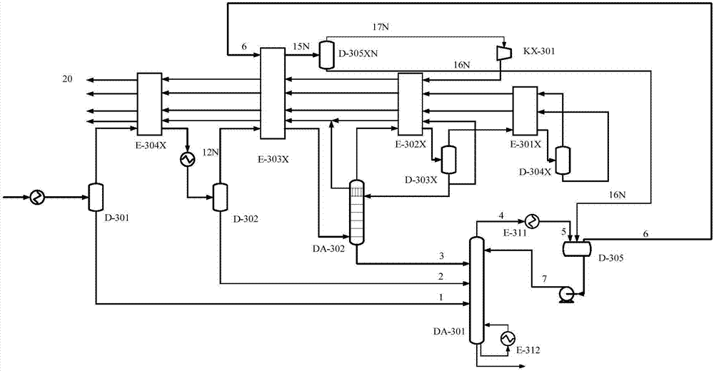
[0071] like image 3 As shown, a demethanizer heat exchange system.

[0072] Including: demethanizer DA-301, demethanizer condenser E-311, demethanizer reflux tank D-305, 1# hydromethane separation tank D-303X, 2# hydromethane separation tank D-304X and cold box, The cold box includes 1# cold box E-301X, 2# cold box E-302X, 3# cold box E-303X and 4# cold box E-304X connected in sequence, and the top outlet of the demethanizer DA-301 is connected to the demethanizer The condenser E-311 is connected to the demethanizer reflux tank D-305, the gas phase outlet of the demethanizer reflux tank D-305 is connected to 2# cold box E-302X, and the liquid phase outlet of the demethanizer reflux tank D-305 is connected to the demethanizer The upper part of DA-301, 2# cold box E-302X is connected to 1# hydrogen methane separation tank D-303X, 2# hydrogen methane separation tank D-304X is connected to 1# cold box E-301X,

[0073] The gas-liquid separation tank D-305XN is installed after th...


PUM


Abstract

The invention discloses a heat exchange system of a demethanizer and a heat exchange method. The heat exchange system adopts one of the following manners: A, a branch separated from an outlet pipeline at the bottom of a 1# hydrogen-methane separation tank is connected with the demethanizer or a demethanizer return tank; B, an aftercooler is arranged at the top of the demethanizer return tank, and a branch separated from the outlet pipeline at the bottom of the 1# hydrogen-methane separation tank is connected with the aftercooler and then connected with the demethanizer return tank; C, a gas-liquid separation tank is arranged behind a cooling box, a gas phase outlet of the demethanizer return tank is connected with the cooling box and then connected with the gas-liquid separation tank, and the bottom of the gas-liquid separation tank is connected with the demethanizer return tank. Under the condition that the coolant level and compressor outlet pressure are unchanged, the gas phase at the top of the demethanizer return tank is cooled by use of local rich cold energy through reasonable optimization of matching of self cold energy of deep cooling, the heat transfer temperature difference of a condenser of the demethanizer is increased, and the loss of ethylene is reduced.

Description

technical field [0001] The invention relates to the field of ethylene production, and more specifically, to a demethanization heat exchange system and a heat exchange method. Background technique [0002] The ethylene plant has the longest process flow and the most complex heat exchange network among chemical plants. As a complex system, its internal use of heat and cooling has a precise match. Ethylene separation can be divided into several areas such as quenching, compression, cold zone, hot zone, refrigeration and utilities. Under the condition of meeting the strict ethylene loss rate, the demethanizer in the cold zone realizes the separation of ethylene and methane hydrogen, which is one of the cores of the whole separation device. [0003] At present, ethylene raw materials are increasingly diversified, and more and more ethylene plants use light raw materials rich in ethane, such as refinery dry gas, to achieve the goals of energy saving, emission reduction, and econo...

Claims


Application Information

Patent Timeline
IPC IPC(8): C07C7/00C07C11/04
CPCC07C7/00C07C11/04
Inventor 彭勃刘永莉李广华王振维
Owner SINOPEC ENG
Learn More