
Particle scattering phase function measuring device and method

A technology of scattering phase function and particle scattering, which is applied in the direction of scattering characteristic measurement, analysis materials, instruments, etc., can solve the problems of large measurement error, accurate acquisition of scattering phase function, etc., achieve less sample volume, reduce measurement error, and simple device Effect

Active Publication Date: 2017-11-14
HARBIN INST OF TECH
View PDF13 Cites 11 Cited by
  • Summary
  • Abstract
  • Description
  • Claims
  • Application Information

AI Technical Summary

Problems solved by technology

[0003] The purpose of the present invention is to solve the large measurement error caused by the influence of the surface reflection of the glass container and the multiple reflection of the internal interface when the detector is placed outside the transparent container in the existing method, and the existing measurement method cannot be used under the condition of a small amount of suspended particle samples. Accurately obtain the problem of its scattering phase function, and propose a particle scattering phase function measurement device and measurement method

Method used


Image

  • Particle scattering phase function measuring device and method
  • Particle scattering phase function measuring device and method
  • Particle scattering phase function measuring device and method

Examples


specific Embodiment approach 1

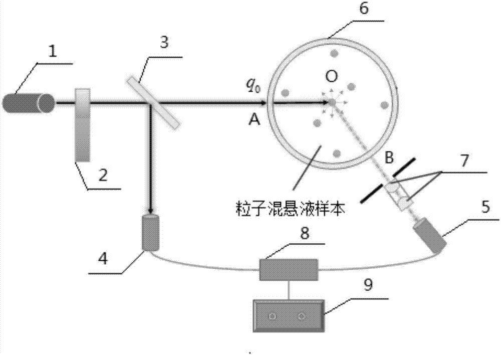
[0022] Specific implementation mode one: combine figure 1 Describe this embodiment, a kind of particle scattering phase function measuring device of this embodiment includes laser (1), optical chopper (2), beam splitter (3), static detector (detector 1) (4), dynamic detector (detector 2) (5), circular cuvette (6), plano-convex lens (7), preamplifier (8) and lock-in amplifier (9);

[0023] The laser (1) emits laser light (reference laser), the laser passes through the chopper (2) and reaches the beam splitter (3), and the laser beam is divided into two beams after passing through the beam splitter (3), and the two beams form an angle of 90 degrees, One of the laser beams normally illuminates the circular cuvette (6) containing the particle suspension, and the dynamic detector (detector 2) (5) measures the particles of the particle suspension in the circular cuvette (6) Department of light intensity signal;

[0024] Two plano-convex lenses (7) are arranged between the dynamic...

specific Embodiment approach 2

[0029] Specific embodiment two: the difference between this embodiment and specific embodiment one is: the convex surfaces of the two plano-convex lenses (7) are arranged oppositely, and the planes of the two plano-convex lenses face the circular cuvette (6) and the dynamic detection respectively. Detector (Detector 2) (5) setting.

[0030] This method can only receive light in the direction perpendicular to the probe, thereby eliminating the influence of stray light.

[0031] First select a laser with a certain wavelength (or other forms of monochromatic light source) according to the needs, the laser emits laser light, the laser light reaches the beam splitter through the chopper, and the laser beam is divided into two beams after passing through the beam splitter, one of which is irradiated in the normal direction The circular cuvette pool is equipped with particle suspension, and then the angle of the dynamic detector (detector 2) is adjusted by a stepping motor to perform...

specific Embodiment approach 3

[0036] Specific implementation mode three: combination Figure 5 To illustrate this embodiment, a particle scattering phase function measurement method of this embodiment is specifically implemented according to the following steps:

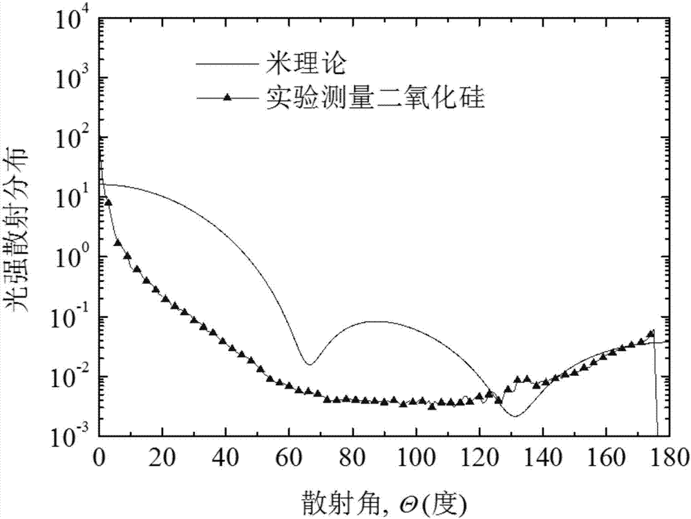
[0037] Step 1. Experimentally measure the scattered light intensity distribution of the standard particle system contained in a transparent circular cuvette under different scattering angles;

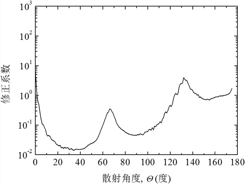
[0038] Step 2. Measure the particle size distribution of the standard particles, calculate the theoretical value of the scattering phase function of the standard particle system through Mie scattering theory, and solve the scattering light intensity distribution of the standard particle system at different scattering angles and the theoretical value of the scattering phase function of the standard particle system The ratio of , to obtain the correction coefficient of the scattering phase function of the standard particle system at different scattering angl...


PUM

PropertyMeasurementUnit
Diameteraaaaaaaaaa

Abstract

The invention relates to a particle scattering phase function measuring device and a measuring method. The invention aims to solve the problems in the conventional method that a big measuring error is caused by influences of surface reflection and inner interface multiple reflection of a glass container when a detector is arranged outside a transparent container and that a scattering phase function cannot be accurately obtained under the condition that the amount of suspended particle samples is small in the conventional measuring method. The measuring method comprises the following steps: 1, measuring scattering light intensity distribution of a standard particle system contained in a transparent circular cuvette under different scattering angles through an experiment; 2, obtaining a correction factor of a scattering phase function of the standard particle system under different scattering angles; and 3, measuring scattering light intensity distribution of a to-be-measured particle system through an experiment, correcting the scattering light intensity distribution of the to-be-measured particle system by utilizing the correction factor of the scattering phase function of the standard particle system, thereby obtaining the scattering phase function of the to-be-measured particle system. The measuring method disclosed by the invention is used for measuring the particle scattering phase function.

Description

technical field [0001] The invention relates to a measuring device and a measuring method of particle scattering phase function. Background technique [0002] The scattering phase function, absorption coefficient, and scattering coefficient of particles constitute the basic radiation characteristic parameters of particle-dispersed media. have important applications. There are two methods of measuring particle scattering phase function, indirect measurement and direct measurement. The indirect measurement method is generally based on the solution of the radiative transfer forward problem combined with the inversion algorithm to obtain the scattering phase function. This method needs to assume a parameterized model of the scattering phase function in advance, and generally cannot obtain the accurate scattering phase function of the particle. For the direct measurement method, the measurement is generally performed by circumferentially arranged detectors, and the scattered l...

Claims


Application Information

Patent Timeline
IPC IPC(8): G01N15/00G01N21/51
CPCG01N15/00G01N21/51
Inventor 赵军明李兴灿刘林华
Owner HARBIN INST OF TECH
Learn More