
End mill with end blade for quickly milling carbon fiber composite

A composite material, high-speed milling technology, applied in the field of machining of difficult-to-machine materials, can solve the problem that cannot be used for milling blind windows, blind slot milling and special-shaped blind holes, reducing chip evacuation and heat dissipation capacity, aggravating thermal damage to composite materials, etc. problems, to reduce cracking and delamination damage, reduce replacement time, improve chip evacuation and heat dissipation

Active Publication Date: 2017-11-21
DALIAN UNIV OF TECH
View PDF12 Cites 19 Cited by
  • Summary
  • Abstract
  • Description
  • Claims
  • Application Information

AI Technical Summary

Problems solved by technology

In order to increase the cutting depth of micro-tooth cutting and improve processing efficiency, Wang Fuji of Dalian University of Technology and others invented the "multi-blade micro-tooth milling cutter for high-speed milling of carbon fiber composite materials", and applied for patent number 201610806761.5. The milling cutter includes Zhou The blade part, the drill tip part and the tool shank part increase the length of the micro-tooth, and the drill tip structure can effectively process windows and through holes, but these two milling cutters cannot be used for milling blind windows, milling blind slots and machining special-shaped Blind hole, so the milling cutter has certain limitations in practical application
Secondly, the milling speed of carbon fiber composite materials is relatively high, generally between 3000r / min and 10000r / min, and the number of cutting edges increases. Chips and heat dissipation, exacerbating the problem of composite thermal damage

Method used


Image

  • End mill with end blade for quickly milling carbon fiber composite
  • End mill with end blade for quickly milling carbon fiber composite
  • End mill with end blade for quickly milling carbon fiber composite

Examples


Embodiment Construction

[0012] The specific implementation of the present invention will be described in detail below in conjunction with the accompanying drawings and technical solutions.

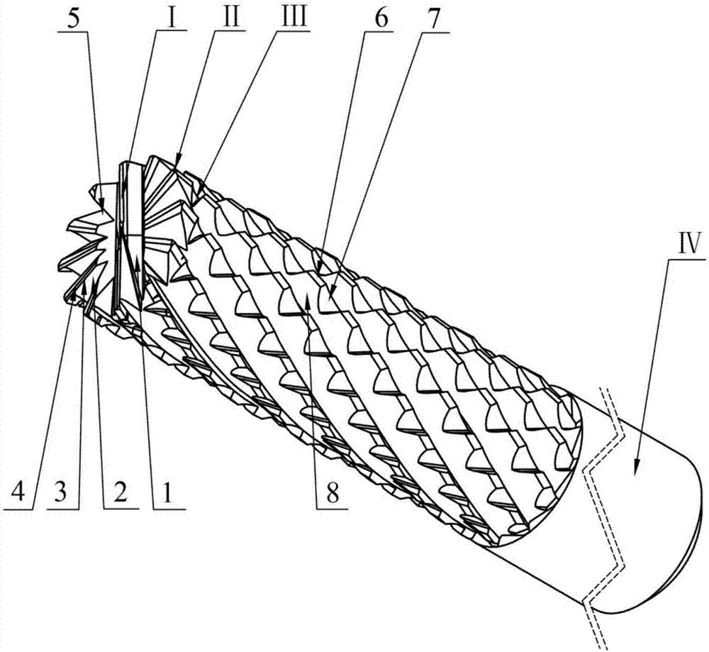
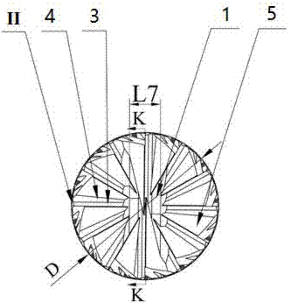
[0013] The band end mill that is used for CFRP high-speed milling of the present embodiment is as figure 1 , figure 2 As shown, the end mill with an end edge is composed of an end edge part I, a peripheral edge part III with a variable chip flute helix angle, a shank part IV, and a transitional circular arc edge II between the peripheral edge and the end edge.

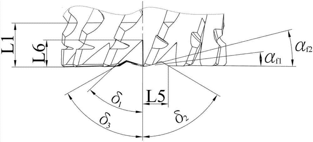
[0014] The end edge part I has a main cutting edge with a rake angle of 0° and a first relief angle of α f1 =7°, the second relief angle α f2 = 14°. The design form of the transition from the end flank flank 3 to the end flank second flank 4 is adopted, the small angle design of the end flank flank 3 and the 0° rake angle of the main cutting edge of the end edge can ensure sufficient strength of the cutting edge , the second flank 4 of the end edge i...


PUM


Abstract

The invention relates to an end mill with an end blade for quickly milling a carbon fiber composite, belongs to the field of cutting machining of materials difficult to be processed and relates to a special cutter for quickly milling a blind slot, a blind window and an irregularly shaped blind hole of the carbon fiber composite. A cutting blade is designed on an end part of a milling cutter of the end mill; end face scrap accommodating slots are formed on the end part; the end mill is composed of an end blade part, a changeable scrap-dividing slot helix angle peripheral blade part, a cutter handle part and a transition arc blade of the peripheral blade and the end blade; two parallel end face scrap accommodating slots are formed on the end blade part; end blade scrap accommodating slots are formed between the blades of the end blade; and the changeable scrap-dividing slot helix angle peripheral blade part has an asymmetrical spiral staggered structure and is equipped with a plurality of tiny teeth staggered by m right-hand spiral grooves and n left-hand spiral grooves. The changeable helical angle scrap-dividing slot is adopted by the end mill, so that the fluttering effect of the cutter while milling can be reduced, the scrap accommodating property while milling is promoted, the heat injury of the composite is reduced and the quick, stable and effective processing for the carbon fiber composite is promoted.

Description

technical field [0001] The invention belongs to the field of cutting processing of difficult-to-machine materials, and relates to a special cutting tool for high-speed milling blind grooves, blind windows and special-shaped blind holes of carbon fiber composite materials. Background technique [0002] Carbon fiber composite material (CFRP) has the characteristics of high specific strength, high specific stiffness, fatigue resistance and corrosion resistance, etc. strength and all-composite structures. With the widespread use of carbon fiber composites in the main load-bearing components of aerospace, based on the requirements of high service reliability in large-scale and complex stress-bearing environments, the quality requirements for machining are also more stringent. Carbon fiber composite material is a typical difficult-to-machine material. It is a mixed form of fiber and resin in the microscopic view, and anisotropic and laminated in the macroscopic view, resulting in...

Claims


Application Information

Patent Timeline
IPC IPC(8): B23C5/10B23C5/16
CPCB23C5/10B23C5/165B23C2226/27B23C2210/326B23C2210/0492B23C5/18B23C2210/0485B23C2210/28
Inventor 王福吉王泽刚贾振元毕广健卢晓红
Owner DALIAN UNIV OF TECH
Learn More