Method for improving fiber laser welding heat efficiency of red copper based on power modulation

A power modulation, fiber laser technology, used in laser welding equipment, welding equipment, manufacturing tools and other directions, can solve the problems of low, no more than 5% at room temperature, high equipment input cost, limited laser application, etc., to improve thermal efficiency, The effect of improving energy transfer efficiency

Inactive Publication Date: 2017-11-21
XI AN JIAOTONG UNIV
View PDF3 Cites 5 Cited by
  • Summary
  • Abstract
  • Description
  • Claims
  • Application Information

AI Technical Summary

Problems solved by technology

However, due to the low absorption rate of copper for infrared lasers with a wavelength of about 1 μm commonly used in industry, it does not exceed 5% at room temperature and can reach about 15% near the melting point.
Therefore, when welding red copper with laser high-energy beam, the required laser power is high. When the thickness of the plate is 1.5mm, the laser power needs to be higher than 2500W to ensure the penetration. The thicker the plate, the higher the laser power required, and the equipment investment cost is t...

Method used


Image

  • Method for improving fiber laser welding heat efficiency of red copper based on power modulation
  • Method for improving fiber laser welding heat efficiency of red copper based on power modulation
  • Method for improving fiber laser welding heat efficiency of red copper based on power modulation

Examples


Embodiment 1

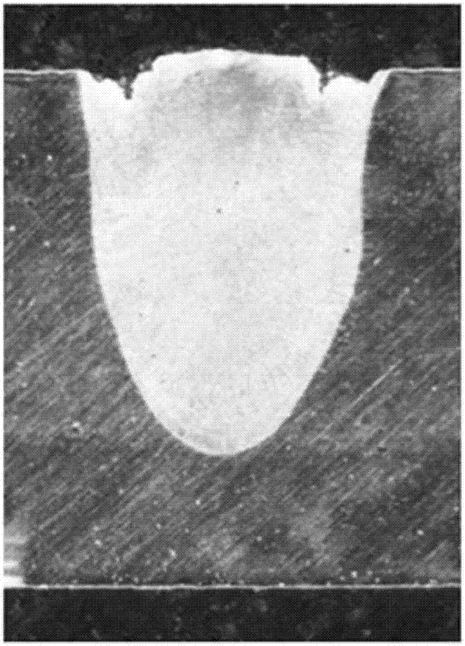
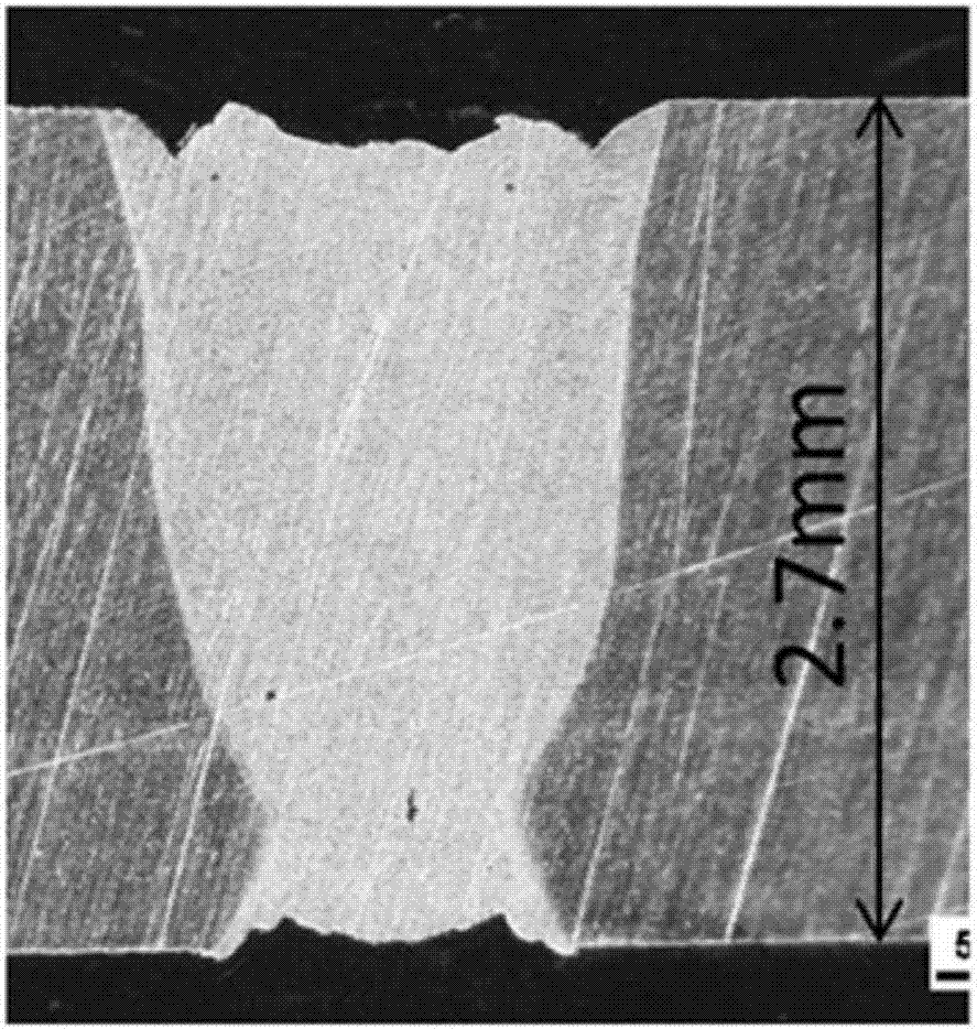
[0025] The test material is AZ31 magnesium alloy, and the thickness of the test plate is 2.7mm. Before the test, the oxide layer on the surface of the material is removed by sanding, and wiped clean with acetone. The welding speed is 5m / min, the defocus is 0mm, and the laser head is inclined at 10° to irradiate the surface of the test plate. The first scheme is: without modulating the laser power, the 2.0kW laser beam is directly irradiated on the surface of the test plate to form a continuous weld bead, and the metallographic sample of the cross-section of the weld is intercepted to obtain the following Figure 2a The results shown; the second scheme is: use sine wave to modulate the laser power, the modulation frequency is 300HZ, the amplitude is 1.5kW, the average power is 2.0kW, to form a continuous weld bead, and intercept the metallographic sample of the weld cross section get as Figure 2b The results shown. from Figure 2a and Figure 2b It can be seen that the met...

Embodiment 2

[0027] The test material is T2 red copper, and the thickness of the test plate is 1.5mm. Before the test, sand the oxide layer on the surface of the material, and wipe it clean with acetone. The welding speed is 1m / min, the defocus is 0mm, and the laser head is tilted at 10° to irradiate the surface of the test plate. The first scheme is: without modulating the laser power, the 2.5kW laser beam is directly irradiated on the surface of the test plate to form a continuous weld bead, and the metallographic sample of the cross-section of the weld is intercepted to obtain the following: Figure 3a The results shown; the second option is: use sine wave to modulate the laser power, the modulation frequency is 100HZ, the amplitude is 1.0kW, and the average power is 2.5kW to form a continuous weld bead and intercept the metallographic sample of the weld cross section get as Figure 3b The results shown. from Figure 3a and Figure 3b It can be seen that the method of laser power mo...


PUM

PropertyMeasurementUnit
Thicknessaaaaaaaaaa
Thicknessaaaaaaaaaa

Abstract

The invention discloses a method for improving the thermal efficiency of copper optical fiber laser welding based on power modulation, which comprises the following steps: providing an I-shaped groove between two pre-butted coppers, and then performing pretreatment on the surface of the I-shaped groove , and then complete the laser welding of two pre-butted coppers based on laser power modulation, wherein the waveform modulation method is used to realize the laser power modulation, which can effectively improve the thermal efficiency of copper fiber laser welding.

Description

technical field [0001] The invention belongs to the field of welding technology, and relates to a method for improving the thermal efficiency of copper optical fiber laser welding based on power modulation. Background technique [0002] Copper has the advantages of excellent electrical conductivity, corrosion resistance and good processing performance. It is widely used in electrical appliances, machinery, vehicles, shipbuilding and civil appliances. It is an indispensable metal for modern industry, agriculture, national defense and science and technology. At present, the welding of copper is done by argon arc welding. The thermal conductivity of red copper is high, which is about 8 times higher than that of ordinary carbon steel. However, the energy density of argon arc welding is low. During the welding process, the base metal is difficult to melt and difficult to weld. The welding deformation is large, and the production environment is harsh. Production efficiency is low...

Claims


Application Information

Patent Timeline
IPC IPC(8): B23K26/24B23K26/60
CPCB23K26/24B23K26/60
Inventor 张林杰杨健楠宁杰白清林裴俊宇刘江哲卢广峰张建勋殷咸青
Owner XI AN JIAOTONG UNIV
Why Eureka
Try Eureka