
Casting and die baking technology for engine cam shaft

A camshaft and engine technology, which is applied in the manufacture of tools, casting molding equipment, casting molds, etc., can solve the problems of increasing the casting cost of camshafts, inconsistent heating and shrinkage, and affecting the quality of camshafts, so as to reduce the scrap rate and improve production efficiency , good thermal conductivity

Active Publication Date: 2017-11-24
ZHEJIANG BOXING IND & TRADE
View PDF9 Cites 2 Cited by
  • Summary
  • Abstract
  • Description
  • Claims
  • Application Information

AI Technical Summary

Problems solved by technology

Before the casting of the camshaft, it is necessary to use coated sand to develop the shape. Usually, qualified molten iron and a qualified model are two prerequisites for obtaining a stable and qualified camshaft blank. When making a mold, the model is usually baked Baking, so that the molding sand is bonded together to form the cavity; but at present, when the model is baked, the model is generally placed directly in the electric donkey for heating, but in this case, because the model has a certain thickness, it is directly placed in the electric donkey Internal baking, the coated sand on the surface of the model is generally heated first, and then the heat is transferred to the inside of the model through thermal diffusion, which will lead to uneven heating of the model, resulting in inconsistent shrinkage during heating and cooling, resulting in deformation and even fracture of the model Become a waste product, seriously affect the quality of the camshaft, and increase the casting cost of the camshaft

Method used


Image

  • Casting and die baking technology for engine cam shaft

Examples


Embodiment 1

[0028] The casting and baking mold process of engine camshaft uses a kind of coated sand and a baking mold furnace. The coated sand comprises: 5% modified phenolic resin, 0.7% urotropine, and 0.35% calcium stearate by mass percentage , silicon-barium alloy 6.5%, alkaline oxide 1.5%, graphene 2.5%, natural silica sand 83.45%; the baking mold furnace includes an oven, the oven is provided with an electromagnetic coil, and the electromagnetic coil is electrically connected with an AC Variable power supply, the frequency of the alternating power supply is adjustable from 30-60Hz, and the voltage is 220V; wherein the alkaline oxides are SiO in parts by mass. 2 : 20-30 parts, CaO: 10-14 parts, BaO: 3-5 parts, CrO: 2-3 parts, MnO: 2-3 parts;

[0029] The baking mold process includes the following steps:

[0030] 1. Place the mold in the mold box, and then place the cold iron to fit the cam surface of the mould;

[0031] 2. Add coated sand to the surface of the mold and smooth the c...

Embodiment 2- Embodiment 4

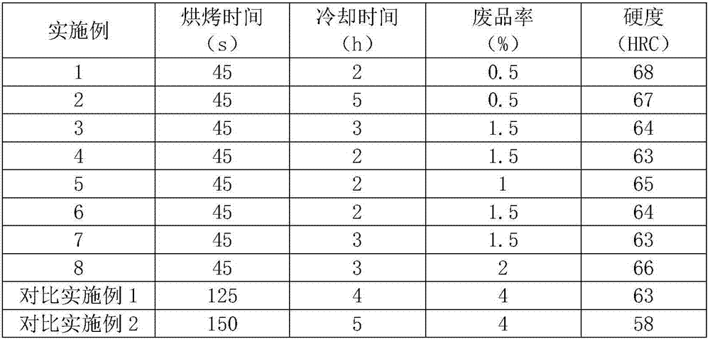
[0042] Compared with embodiment 1, the difference between embodiment 2-embodiment 4 is that the baking mold before casting the engine camshaft is carried out according to the parameters in table 1.

Embodiment 5

[0044] Compared with Example 1, the difference of Example 5 is that the engine camshaft is baked according to the parameters in Table 1 before casting; and in step 3, the frequency of 30 Hz is directly heated for 45 seconds.


PUM


Abstract

The invention discloses a casting and die baking technology for an engine cam shaft. The technology comprises the steps that firstly, a die is placed in a die box, and then a chilling block is placed to be attached to the cam face of the die; secondly, precoated sand is added to the surface of the die and is leveled; thirdly, the die box is placed in an oven, an oven door is closed, the frequency of an alternating power source is adjusted to 35-55 Hz, baking is conducted for 30-60 s, the alternating power source is turned off, and the die box is naturally cooled to 100 DEG C-150 DEG C in the oven; and fourthly, the die box is taken out of the oven, natural cooling is conducted to the normal temperature, and the die is taken out. By means of the casting and die baking technology, when a model is baked, moulding sand can be heated more evenly, contraction is consistent during cooling, the rejection rate of the model is reduced, and the casting quality of the cam shaft is improved.

Description

technical field [0001] The invention relates to the technical field of engine component manufacturing, in particular to a casting baking process of an engine camshaft. Background technique [0002] The camshaft is a component in a piston engine that controls the opening and closing of the valves. The rotation speed of the camshaft in the engine is generally very high, and it needs to bear a large torque, so the requirements for the strength and support of the camshaft are very high; and the cam bearing is subjected to periodic impact loads, the contact between the cam and the tappet The contact stress is very large, and the relative sliding speed is also high, so the wear of the cam working surface is serious. Therefore, in addition to high dimensional accuracy, small surface roughness and sufficient rigidity, the camshaft journal and the cam working surface should also have high wear resistance and good lubricity. [0003] The camshaft is generally cast iron, which is pro...

Claims


Application Information

Patent Timeline
Patent Type & Authority Applications(China)
IPC IPC(8): B22C9/14B22C1/02B22C1/22B22D27/18
CPCB22C1/02B22C1/2253B22C9/12B22D27/18
Inventor 陈晖周望平周康康徐刚强胡火明汤荣曹毅蒋文龙黄吉祥赵家贵何飞李高国
Owner ZHEJIANG BOXING IND & TRADE
Learn More