A cyclohexane oxidation reactor and its use method

An oxidation reactor, cyclohexane technology, applied in the preparation of oxidation reaction, chemical instruments and methods, chemical methods for reacting liquid and gas medium, etc. It can improve the flow conditions and improve the selectivity of the problems such as the increase of gas holdup.

Active Publication Date: 2021-06-04
CHINA PETROLEUM & CHEM CORP +1
View PDF17 Cites 0 Cited by
  • Summary
  • Abstract
  • Description
  • Claims
  • Application Information

AI Technical Summary

Problems solved by technology

However, this reactor also adopts multi-stage air intake. When air oxidation is used, because the gas contains a large amount of nitrogen, the gas holdup of the upper material in the straight barrel section will increase significantly, thereby deteriorating the flow state in the reactor; The gas from the gas distributor on the upper part of the straight barrel section of the device will escape from the liquid phase after a short period of time, and the oxygen content in the tail gas may exceed the safety limit due to the short residence time

Method used


Image

  • A cyclohexane oxidation reactor and its use method
  • A cyclohexane oxidation reactor and its use method
  • A cyclohexane oxidation reactor and its use method

Examples


Embodiment 1

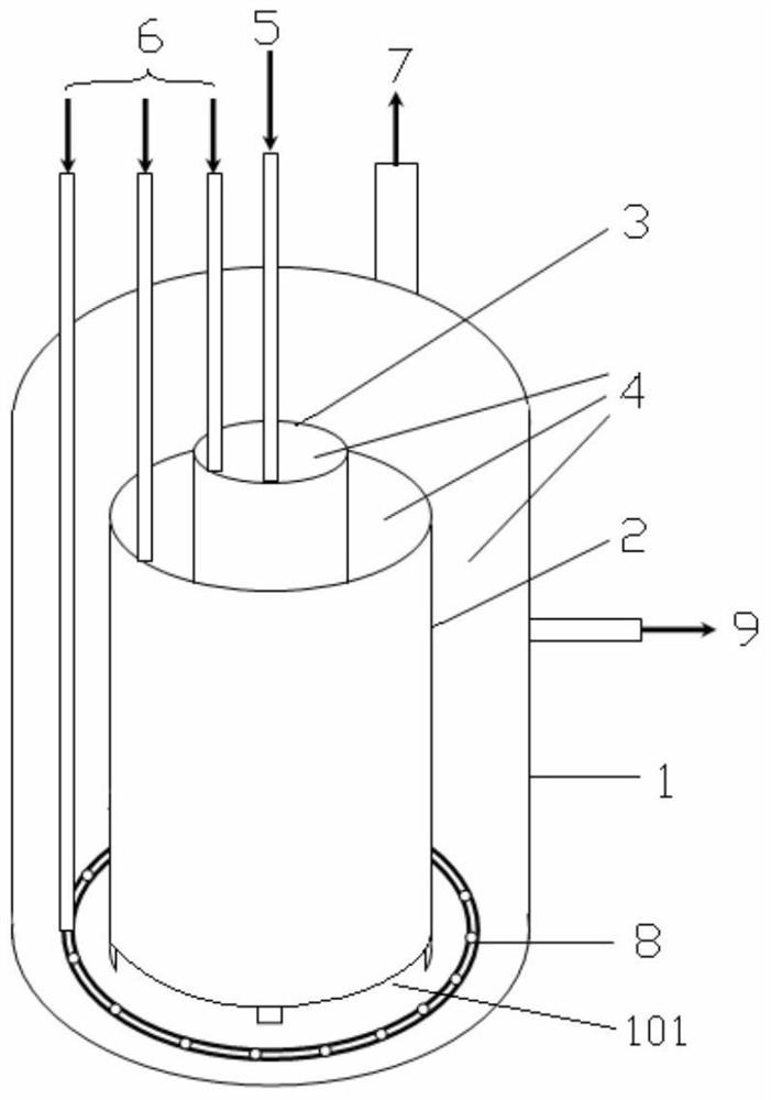
[0047] see figure 1 , the reactor housing 1 of the cyclohexane oxidation reactor is sleeved with a multi-layer guide tube, which is a two-layer guide tube in this embodiment, including a first guide tube 3 located in the center and a second guide tube located on the outside Flow tube 2, two flow guide tubes are arranged coaxially with the reactor shell 1, and have different diameters, which divide the reactor shell 1 into a three-stage annular area 4, and the height of the flow guide tubes is stepped from the center to the outside Lower, and the bottom of the first draft tube 3 and the second draft tube 2 and the bottom of the reactor shell 1 leave a water gap 101, so that the three-stage annular area can pass through the draft tube and the bottom of the shell The water gap 101 between them flows step by step, and can also be overflowed in series through the top step by step. The first guide tube 3 in the center is connected to the liquid inlet 5, and the annular area 3 of eac...

Embodiment 2

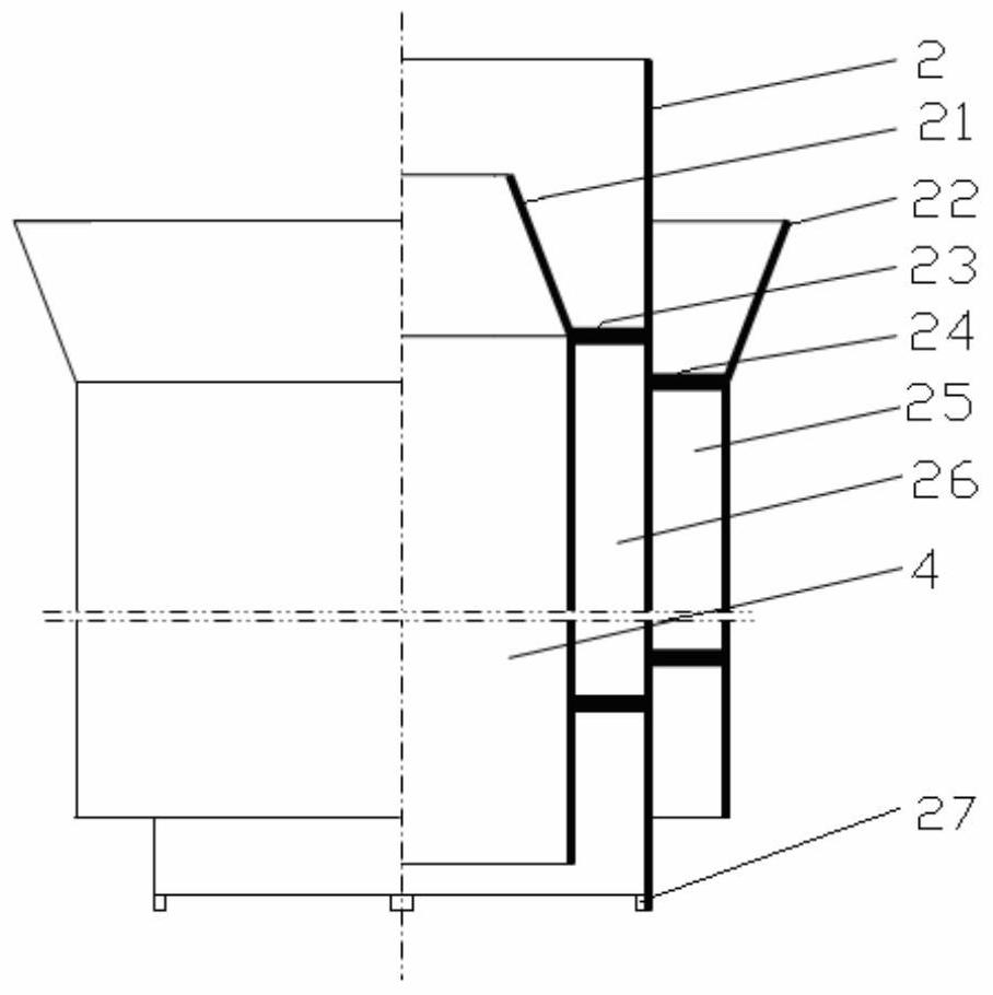
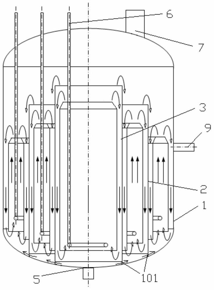
[0055] see in conjunction figure 2 with image 3 , the structure of the reactor in this example is the same as in Example 1, the difference is that the draft tube in this example is a double-loop flow guide tube, specifically as figure 2 As shown, taking the second guide tube 2 as an example to illustrate the structure of the double circulation guide tube, the inner wall and the outer wall of the second guide tube 2 are coaxially fixed with a cylindrical inner circulation baffle 21 and an outer circulation flow The baffle 22, two circulation baffles are respectively fixed on the inner side and the outer side of the second flow guide tube 2 by the inner circulation fixing rib 23 and the outer circulation fixing rib 24, between the inner circulation baffle 21 and the second flow guide tube 2 1. An inner circulation area 26 and an outer circulation area 25 that circulate up and down are formed between the outer circulation baffle plate 22 and the second guide tube 2, and the i...


PUM

PropertyMeasurementUnit
diameteraaaaaaaaaa

Abstract

The invention discloses a cyclohexane oxidation reactor and a method for using the same. The reactor shell is sleeved with multi-layer guide tubes, each guide tube has a different diameter, and the inside of the reactor shell is divided into multi-stage annular areas. There is a water gap between the bottom of each draft tube and the reactor shell, and the height of the draft tube decreases step by step from the center to the outside. The central draft tube is connected to the liquid inlet, and the annular area of ​​each stage and The air guide tube in the center is connected to the air inlet, the outermost annular area is connected to the liquid outlet, and the top of the reactor shell is provided with an air outlet. In the reactor of the present invention, at least half of the liquid-phase cyclohexane flows through the gap between the bottom of the draft tube and the reactor shell layer by layer, and no more than half of the liquid-phase cyclohexane flows through the top of the draft tube. Overflow layer by layer. The invention improves the flow condition of the cyclohexane in the reactor, improves the selectivity of the process, and can increase the oxidation selectivity of the cyclohexane by 1.5% to 3.0% compared with the prior art.

Description

technical field [0001] The invention relates to a cyclohexane oxidation reactor and a using method thereof. Background technique [0002] To prepare cyclohexanol and cyclohexanone, cyclohexane is usually oxidized with a gas containing molecular oxygen, first to generate an oxidation mixture (cyclohexane oxidation solution) containing cyclohexyl hydroperoxide, cyclohexanol and cyclohexanone, and then treat this An oxidation mixture is used to decompose the cyclohexyl hydroperoxide to generate cyclohexanol and cyclohexanone. The reaction product is subjected to multiple rectifications to obtain cyclohexanol and cyclohexanone, and the cyclohexane is recycled. [0003] The cyclohexane oxidation reactor is generally a bubble tower, and internal components such as a draft tube can be added to the tower to improve mass transfer, and agitation can also be added. In the bubble column, it is generally not necessary to vigorously stir the liquid phase, the gas phase can be highly disp...

Claims


Application Information

Patent Timeline
Patent Type & Authority Patents(China)
IPC IPC(8): B01J10/00B01J19/00B01J19/24C07C27/12C07C29/50C07C35/08C07C45/33C07C49/403C07C407/00C07C409/14
CPCB01J10/002B01J19/0053B01J19/006B01J19/245B01J2219/0004B01J2219/00164B01J2219/00765B01J2219/1943C07C29/50C07C45/33C07C407/00C07C35/08C07C49/403C07C409/14
Inventor 周小文刘洪武黎树根
Owner CHINA PETROLEUM & CHEM CORP
Why Eureka
Try Eureka