Space fluid velocity and pressure synchronous measurement system based on pressure-sensitive particle light intensity measurement

A fluid velocity and synchronous measurement technology, applied in the direction of measuring devices, instruments, etc., can solve the problems of complex flow field and increased pressure distribution of pneumatic components

Active Publication Date: 2018-02-02
SHANGHAI JIAO TONG UNIV
View PDF7 Cites 21 Cited by
  • Summary
  • Abstract
  • Description
  • Claims
  • Application Information

AI Technical Summary

Problems solved by technology

[0004] With the development of aerodynamics, the structure of the aerodynamic components and their flow fields in the research topic are becoming more and more complex, and the unsteady characteristics of the flow field changing with time are becoming more and more prominent. A deep understanding of the unsteady flow field has become a top priority. For space There are more and more studies on the pressure distribution inside the flow field, but there is no measurement method that can directly measure the pressure distribution of the fluid in the space in the prior art

Method used


Image

  • Space fluid velocity and pressure synchronous measurement system based on pressure-sensitive particle light intensity measurement
  • Space fluid velocity and pressure synchronous measurement system based on pressure-sensitive particle light intensity measurement
  • Space fluid velocity and pressure synchronous measurement system based on pressure-sensitive particle light intensity measurement

Examples


Embodiment 1

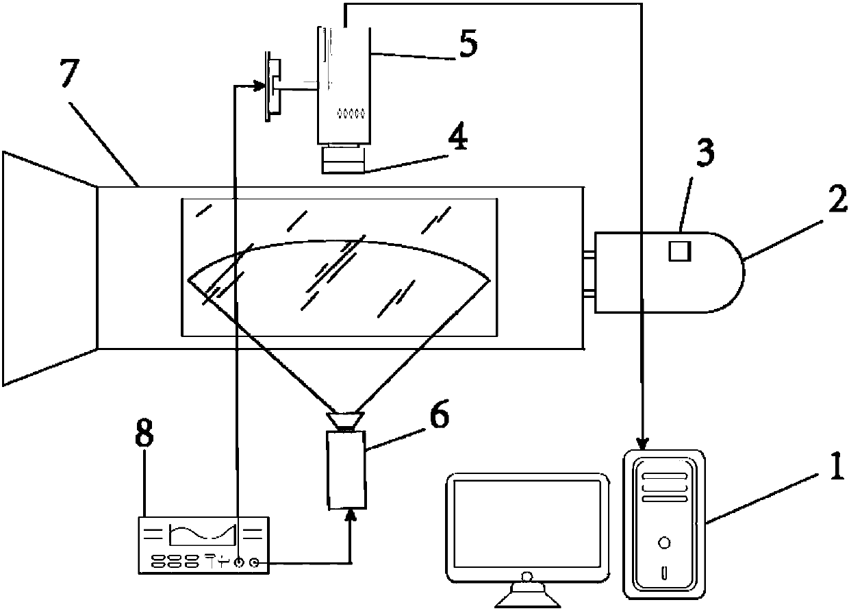
[0042] Such as figure 1 As shown, the space fluid velocity pressure synchronous measurement system based on pressure-sensitive particle light intensity measurement includes a signal transmitter 8, a pulsed laser generator (that is, a 400nm laser generator) 6 electrically connected to the signal transmitter 8, a particle source 3, A particle generator 2 used in conjunction with a particle source 3, and an image processing unit, the image processing unit includes a filter 4, a high-speed CCD camera 5, a computer 1 connected to the high-speed CCD camera 5;

[0043] Among them, the pressure-sensitive particles include hollow SiO 2 Particles, Hollow SiO 2 Pressure-sensitive luminescent molecules are adsorbed on the surface of the particles, and distributed into the space to be measured through the particle generator 2 .

[0044] In this embodiment, the size of the pressure-sensitive particle is 10 μm, and the attached pressure-sensitive luminescent molecule is PtTFPP. The prepar...

Embodiment 2

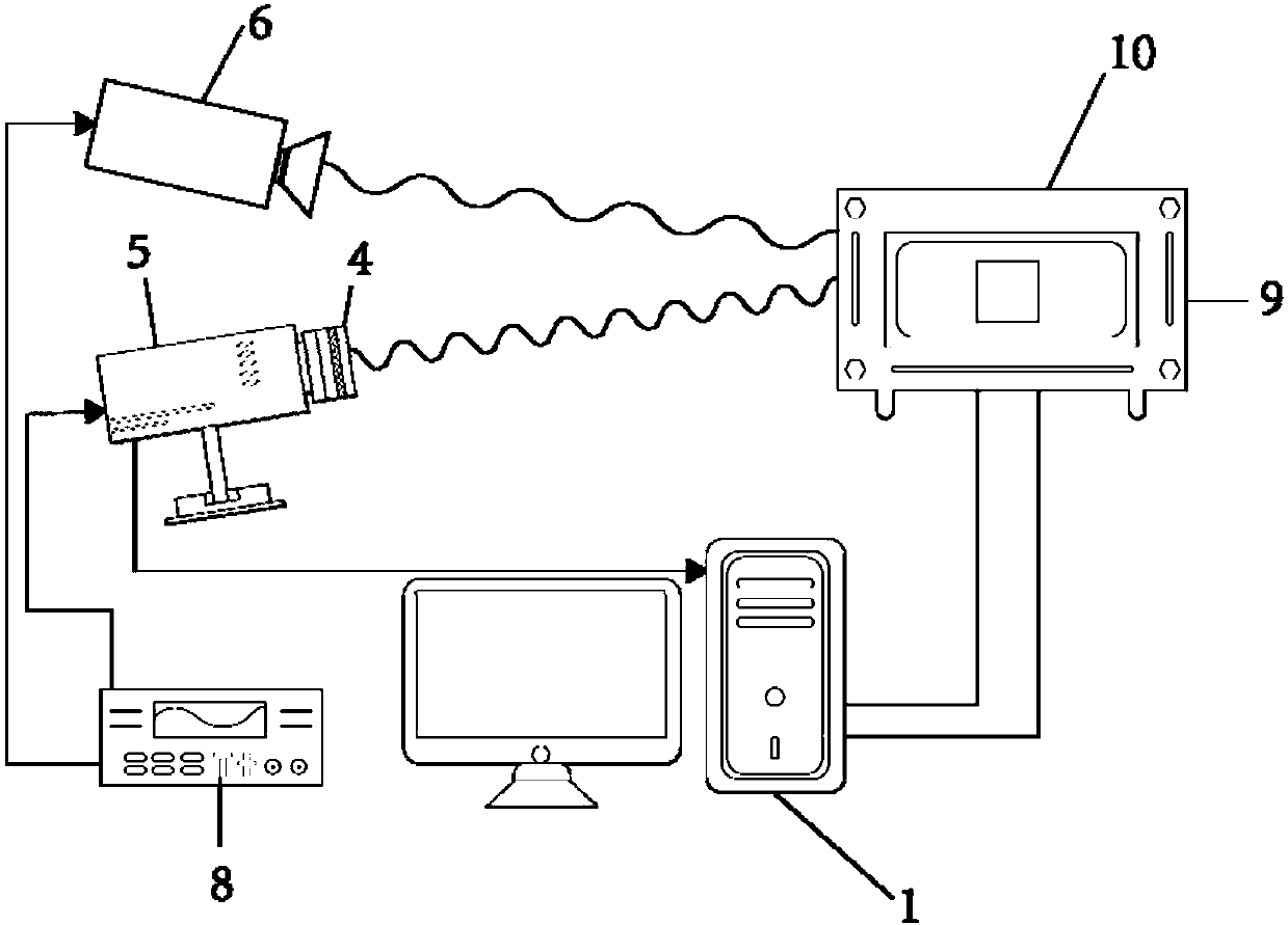
[0056] Such as figure 2 As shown, the pressure calibration system of the present invention includes a signal transmitter 8, a 400nm laser generator 6 electrically connected to the signal transmitter 8, a pressure-sensitive particle sample 9, a pressure control box 10, and an image processing unit. This image processing unit comprises filter mirror 4, high-speed CCD camera 5, the computer 1 that is connected with high-speed CCD camera 5

[0057] Firstly, the pressure-sensitive luminescent molecules were dissolved in dichloromethane solvent, and then hollow SiO 2 particles (control concentration is 0.15g / mL), and then the pressure-sensitive dye photons are adsorbed on the hollow SiO by ultrasonic vibration. 2 Particles, filtered and evaporated to dryness.

[0058] Wherein, dichloromethane is used as solvent, and the concentration of PtTFPP is 2mg / ml and Ru(dpp) respectively. 3 A solution with a concentration of 1 mg / ml. Two sizes of particles (wherein the larger particle ha...

Embodiment 3

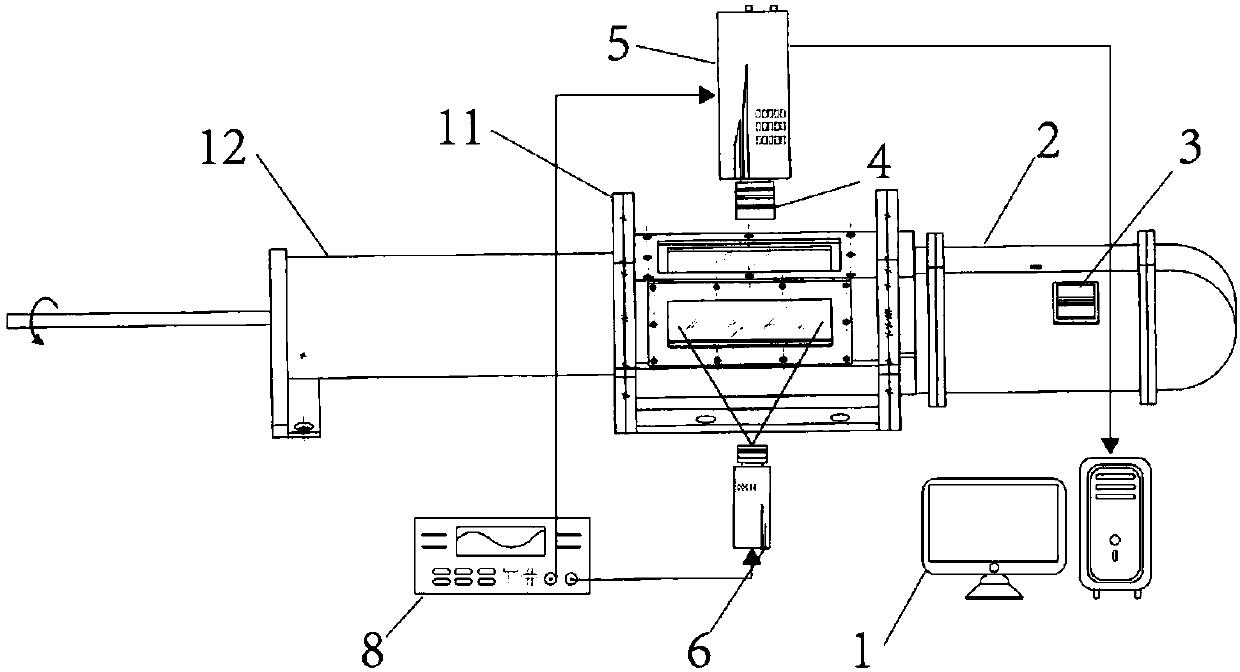
[0062] Such as image 3 The present invention is shown in the structure diagram of the adjustable space flow field measurement system, the measurement system includes a signal transmitter 8, a pulsed laser generator 6 electrically connected to the signal transmitter 8, a particle source 3, used in conjunction with the particle source 3 The particle generator 2, and the image processing unit, the image processing unit includes a filter 4, a high-speed CCD camera 5, a computer 1 connected to the high-speed CCD camera 5, and a piston 12 and a piston sleeve 11 for controlling pressure.

[0063] In this embodiment, the size of the pressure-sensitive particle is 2 μm, and the attached pressure-sensitive luminescent molecule is PtTFPP.

[0064] In this embodiment, the pressure in the flow field of the pressure stabilizing space is adjusted by controlling the piston.

[0065] In the working state, the pressure-sensitive particles in the particle source 3 are evenly implanted into the...


PUM


Abstract

The invention relates to a space fluid velocity and pressure synchronous measurement system based on pressure-sensitive particle light intensity measurement. The system comprises a signal emitter, a pulse laser generator connected with the signal emitter, a high-speed CCD camera arranged opposite to the pulse laser generator and connected with the signal emitter, and a computer for receiving and processing digital image signals of the high-speed CCD camera. A flow field to be measured is arranged between the pulse laser generator and the high-speed CCD camera; the flow field to be measured isconnected with a particle generator for uniformly injecting pressure-sensitive particles to the flow field to be measured; and the front end of the high-speed CCD camera is equipped with an optical filter. Compared with the prior art, the system has the capability of capable of measuring pressure and velocity distribution in a space simultaneously; in the test process, the pressure-sensitive particles are light in weight and small in size, and can be injected to the flow field without influencing flow of the flow field, so that velocity distribution and pressure distribution in the flow fieldcan be measured directly; and the measurement method is direct and convenient, and is wide in application range.

Description

technical field [0001] The invention relates to the technical field of inorganic optical materials, in particular to a space fluid velocity and pressure synchronous measurement system and method based on pressure-sensitive particle light intensity measurement. Background technique [0002] At present, in the prior art, there is no measurement method that can simultaneously measure the velocity distribution and pressure distribution of the flow field in the space. [0003] The measurement method of the surface pressure of the object in the flow field has the optical pressure-sensitive coating measurement technology that began in the 1980s. This technology combines the latest research results of polymer chemistry, optics and other disciplines, and uses the "photoluminescence" effect of a certain polymer compound to undergo a quantum energy step under the irradiation of light of a specific wavelength and the "oxygen" that returns to the ground state. Quenching” phenomenon, thr...

Claims


Application Information

Patent Timeline
Patent Type & Authority Applications(China)
IPC IPC(8): G01D21/02
Inventor 彭迪谷丰焦灵睿刘应征
Owner SHANGHAI JIAO TONG UNIV
Why Eureka
Try Eureka