
Waste solvent oil separation process

A technology for separation of waste solvent and oil, applied in distillation purification/separation, hydrocarbon purification/separation, carboxylate separation/purification, etc., which can solve the problems of secondary pollution, high energy consumption, and poor renewability of water resources. , to achieve a good effect of recycling and separation

Active Publication Date: 2018-02-16
XINZHONGTIAN ENVIRONMENTAL PROTECTION
View PDF8 Cites 6 Cited by
  • Summary
  • Abstract
  • Description
  • Claims
  • Application Information

AI Technical Summary

Problems solved by technology

The dilution method uses a large amount of water to dilute the waste solvent, which not only causes waste of water resources, but also causes new water pollution, and the renewability of polluted water resources is extremely poor. Therefore, this method is not advisable.
The incineration method is to directly burn the waste solvent oil. Although it can completely treat the liquid waste, the incineration method must meet the standard, and the process requirements are very strict. If the incineration process does not meet the standard, it will produce more serious secondary pollution.
The vacuum distillation method uses a vacuum distillation tower to recover the main components in the waste solvent oil, mainly by reducing the pressure inside the tower to reduce the solvent volatilization temperature, and the recovery effect is better, but the vacuum distillation equipment requires high air tightness, and the production time Large energy consumption, large investment, obvious disadvantages
Therefore, at present, there is no simple and low-cost way to recycle waste solvent oil containing xylene and butyl acetate.

Method used


Image

  • Waste solvent oil separation process
  • Waste solvent oil separation process

Examples


Embodiment Construction

[0024] The present invention will be further described in detail below through specific implementations:

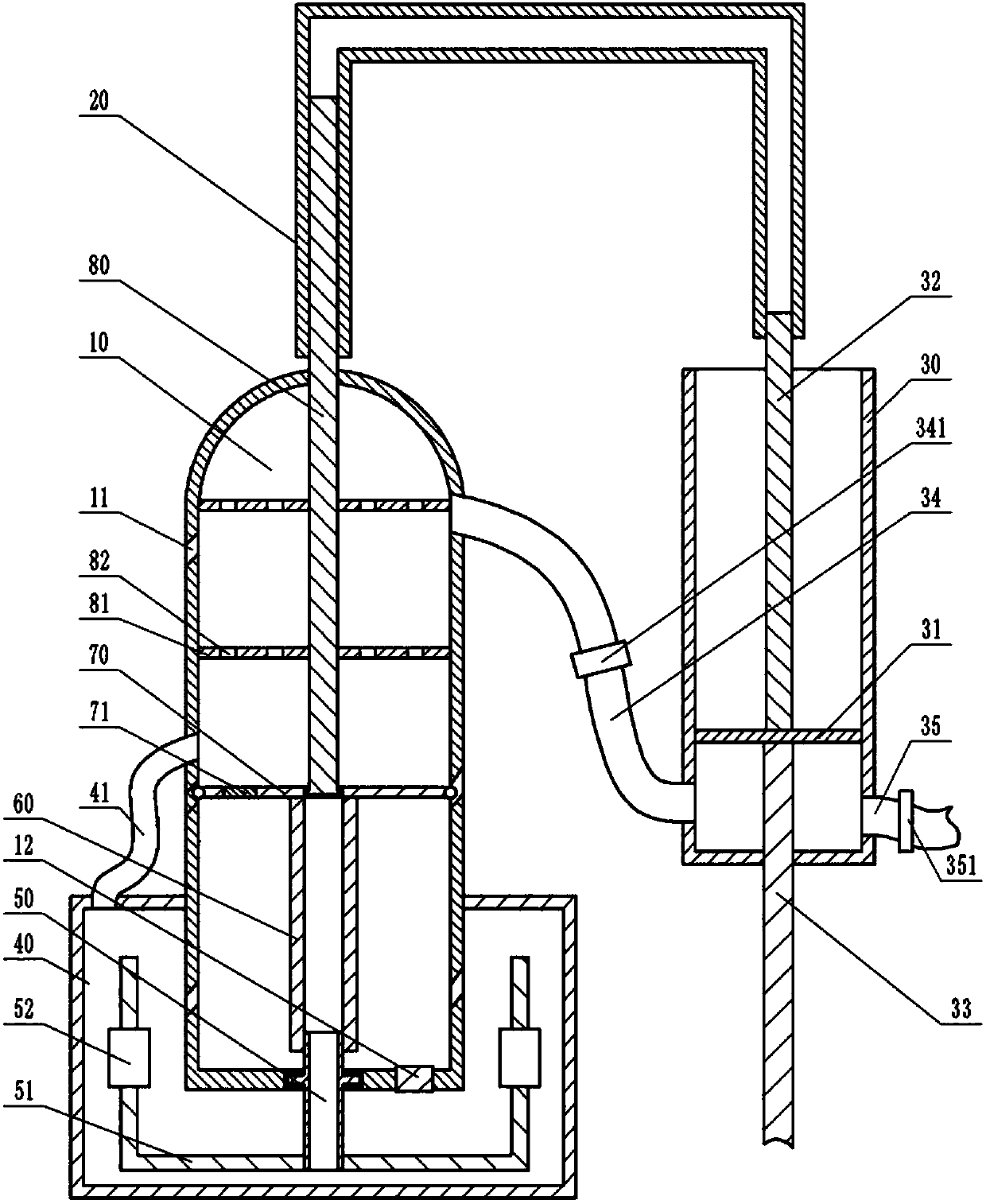
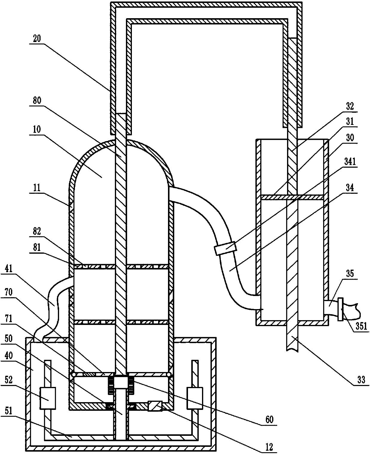
[0025] Instruction attached Figure 1 to 2 The reference signs in include: distillation tank 10, groove 11, pressure valve 12, communicating device 20, storage cylinder 30, piston 31, push column 32, piston rod 33, discharge pipe 34, one-way discharge valve 341 , Feed pipe 35, one-way feed valve 351, intermediate tank 40, exhaust pipe 41, connecting pipe 50, stirring shaft 51, heating device 52, telescopic pipe 60, pressure plate 70, one-way door 71, pressure column 80, Slow flow plate 81, through hole 82.

[0026] A waste solvent oil separation process includes the following steps:

[0027] (1) Distillation at room temperature: Use a distillation device to distill the waste solvent oil at room temperature to obtain a liquid containing xylene and butyl acetate by distillation. Such as figure 1 , figure 2 As shown, the distillation device includes a storage cylinder 30, a com...


PUM


Abstract

The invention belongs to the technical field of solvent recovery and particularly discloses a waste solvent oil separation process. The waste solvent oil separation process comprises the following steps: (1) performing normal temperature distillation, namely performing normal temperature distillation on waste solvent oil by adopting a distilling apparatus, and distilling to obtain liquid containing xylene and n-butyl acetate; (2) performing magnetization treatment, namely pumping the liquid obtained in the step (1) into a closed magnetization pipe to perform circulating magnetization treatment, and circulating for 4-8 times; (3) performing intermittent fractionation, namely performing intermittent fractionation on the liquid obtained in the step (1) in a rectifying tower reactor, opening condensate water, connecting a heating power supply, and heating the tower reactor, wherein the rectification parameters are set as follows: the usage amount of circulation cooling water of 48-60m<3> / h, the steam pressure of 0.5-0.7MPa and steam consumption of 0.3-0.5t / h; (4) performing tail gas treatment. According to the process for separating waste solvent oil, the cost is low, the operation issimple, the waste solvent is subjected to repeated distillation operations, and the waste solvent can be effectively recycled.

Description

Technical field [0001] The invention belongs to the technical field of solvent recovery, and particularly relates to a waste solvent oil separation process. Background technique [0002] In industrial production, a large amount of waste solvents are generated, and the direct discharge of these waste solvents will pollute the environment, so these waste solvents are usually treated before discharge. Some solvents in the waste solvents can be recycled, and the recovered solvents can be reused in industrial production, saving the production cost of enterprises. For example, the main components of waste solvents produced by automobile manufacturers are xylene and butyl acetate. Xylene has high economic value, and its price has risen from 4000 yuan / ton to the current 10000 yuan / ton, while the current price of butyl acetate It has also reached 7000-11000 yuan / ton. [0003] At present, waste solvents are generally treated by methods such as "dilution", "incineration, and vacuum distilla...

Claims


Application Information

Patent Timeline
Patent Type & Authority Applications(China)
IPC IPC(8): C07C7/00C07C7/04C07C15/08C07C67/48C07C67/54C07C69/14B01D3/14B01D3/32
CPCB01D3/14B01D3/32C07C7/005C07C7/04C07C67/48C07C67/54C07C15/08C07C69/14
Inventor 马泽州阳杨胡茂丽张瑜郑泽杨贵林
Owner XINZHONGTIAN ENVIRONMENTAL PROTECTION
Learn More