Multi-stage cutting drainage air distribution device, drying chamber and dryer

A technology of air distribution device and drying room, which is applied in the field of direct-fired chain plate hot air tunnel drying room and dryer, and can solve the problems of difficulty in changing and adjusting fan operating parameters, complex and targeted design and calculation, and reduction Reliance on small air volume and wind pressure to achieve the effect of improving fuel utilization rate and temperature control response ability, compact structure, and low running resistance

Pending Publication Date: 2018-02-23
江毓铭
View PDF0 Cites 7 Cited by
  • Summary
  • Abstract
  • Description
  • Claims
  • Application Information

AI Technical Summary

Problems solved by technology

The form of uniform opening is to form a damping effect in the air chamber with a large air volume and air pressure to avoid the segregation of hot air to achieve the effect of uniform air distribution. Its essence is to rely on a large air volume to achieve uniform distribution of hot air. High circulation fans are used to stabilize the air volume and pressure of the air chamber, resulting in a large waste of kinetic energy. At the same time, there are disadvantages such as small operation adjustable capacity, and small adaptability to different drying varieties and different dry humidity, especially for heat sensitivity. It is difficult to adjust the drying of materials, and it is not suitable for drying light materials; from the perspective of equipment, the air chamber with large air volume and pressure also needs to strengthen the structural strength of the air plate
In order to overcome the above weaknesses, on the basis of the uniform hole opening air distribution device, a variable opening ratio punching plate is developed, which reduces the running resistance, reduces the air volume and pressure, and reduces the energy consumption of the fan. However, this structure is still It is the principle of using the air chamber composed of perforated plates or hole caps to form a damping effect to avoid hot air segregation; the design of the inclined air distribution plate with variable opening ratio needs to simulate the trajectory of hot air under a certain air volume and pressure to arrange changing openings Aperture and spacing require more complex targeted design and calculation; the dependence on air volume and pressure is greatly reduced, and the useless power consumption of fans is reduced, but the pertinence of drying conditions is increased, and the adaptability to changes is reduced. It is not easy to change and adjust the fan operating parameters
Both of the above two methods have the disadvantages that the dust of the dried materials is easy to accumulate in the air chamber to further pollute the fresh dried materials, and there is a disadvantage of difficult cleaning

Method used


Image

  • Multi-stage cutting drainage air distribution device, drying chamber and dryer
  • Multi-stage cutting drainage air distribution device, drying chamber and dryer
  • Multi-stage cutting drainage air distribution device, drying chamber and dryer

Examples


Embodiment

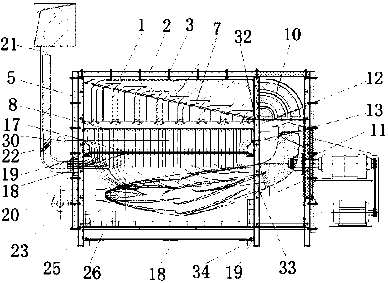
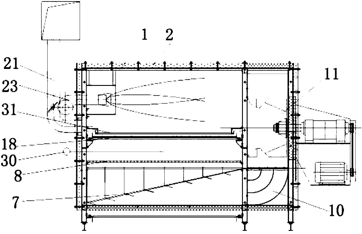
[0039] figure 1 It is a structural schematic diagram of the down blowing hot air drying chamber of the present invention. From figure 2 and figure 1 It can be clearly seen that the difference between the down blowing hot air drying room and the up blowing hot air drying room is that the starting units in the left area and the right area are different from bottom to top, but the order of each unit is is consistent. Let's take the hot air drying room as an example to illustrate.

[0040] The down-blowing hot air drying chamber roughly includes five functional units: a direct-fired heating unit (referred to as a combustion chamber), a hot air mixing booster unit, a multi-stage uniform air unit, a through-flow drying unit, a negative pressure dehumidification unit and an automatic control unit. . Among them, the direct-fired heating unit, the hot air mixing booster unit, the multi-stage uniform air unit, and the through-flow drying unit are arranged inside the drying chamber...


PUM


Abstract

The invention discloses a multi-stage cutting and drainage air distribution device, which includes a diversion wind bucket, an air distribution plate and an air uniform plate; The knife edge of the first-level wind deflector of each arc-shaped wind-cutting deflector is located on one side of the air inlet; the air distribution plate is composed of several movable wind-cutting deflectors; The blades of the wind plates are all facing the side where the air outlet of the air guide funnel is located, and the structure of the movable wind cutting deflector meets the requirements of being able to guide the wind direction to a vertical direction; Vertically below or above the air outlet of the air distribution panel. The present invention discloses a drying chamber and a drying machine comprising the multi-stage cutting drainage air distribution device.

Description

technical field [0001] The invention relates to the field of drying machinery and equipment, in particular to a direct-fired chain plate bed hot air tunnel drying chamber and a drying machine. Background technique [0002] The chain plate hot air tunnel dryer is a common through-flow dryer. The hot air used as the drying medium is usually produced by the air heated by the preheater. According to the heating method, it can be divided into two categories: one is the indirect heat exchange method, that is, the air is heated by steam or heated heat transfer oil through the partition heat exchanger; the other is the direct heating method, that is, flammable gas, liquid, etc. Or the high-temperature flue gas produced by solid combustion is directly used as a drying medium, and commonly used equipment such as a hot blast stove. The hot blast stove method of direct heating solves the loss of multiple transfers of heat energy and improves the efficiency of heat energy use. [0003]...

Claims


Application Information

Patent Timeline
Patent Type & Authority Applications(China)
IPC IPC(8): F26B15/12F26B21/00F26B25/00
CPCF26B15/12F26B21/001F26B21/004F26B25/00F26B25/002
Inventor 江毓铭江悦刘常红
Owner 江毓铭
Why Eureka
Try Eureka