Gas-liquid separator for gas treatment

A gas-liquid separator and gas treatment technology, which is applied in the direction of separation methods, dispersed particle separation, chemical instruments and methods, etc., can solve the problems of increased energy consumption, harmful equipment, poor separation effect, etc., and achieve the goal of improving efficiency and enhancing effect Effect

Inactive Publication Date: 2018-02-27
邹德学
View PDF0 Cites 0 Cited by
  • Summary
  • Abstract
  • Description
  • Claims
  • Application Information

AI Technical Summary

Problems solved by technology

This technology is widely used in petroleum, chemical industry (such as the purification and separation of raw material gas in the production of synthetic ammonia, nitric acid and methanol, and the desulfurization of circulating hydrogen for repeated use in hydrogenation units), natural gas exploitation, storage and transportation and deep processing, recovery of diesel hydrogenation tail gas, Wet desulfurization, flue gas waste heat utilization, wet dust removal and fermentation engineering processes are used to separate and remove harmful substances or efficiently recover useful substances; in the past gas-liquid separation process, the gas-liquid separation effect is poor, and the liquid is often carried into the air pump, increasing energy consumption and endangering equipment, and even being discharged into the atmosphere, causing environmental pollution

Method used


Image

  • Gas-liquid separator for gas treatment
  • Gas-liquid separator for gas treatment

Examples


Embodiment Construction

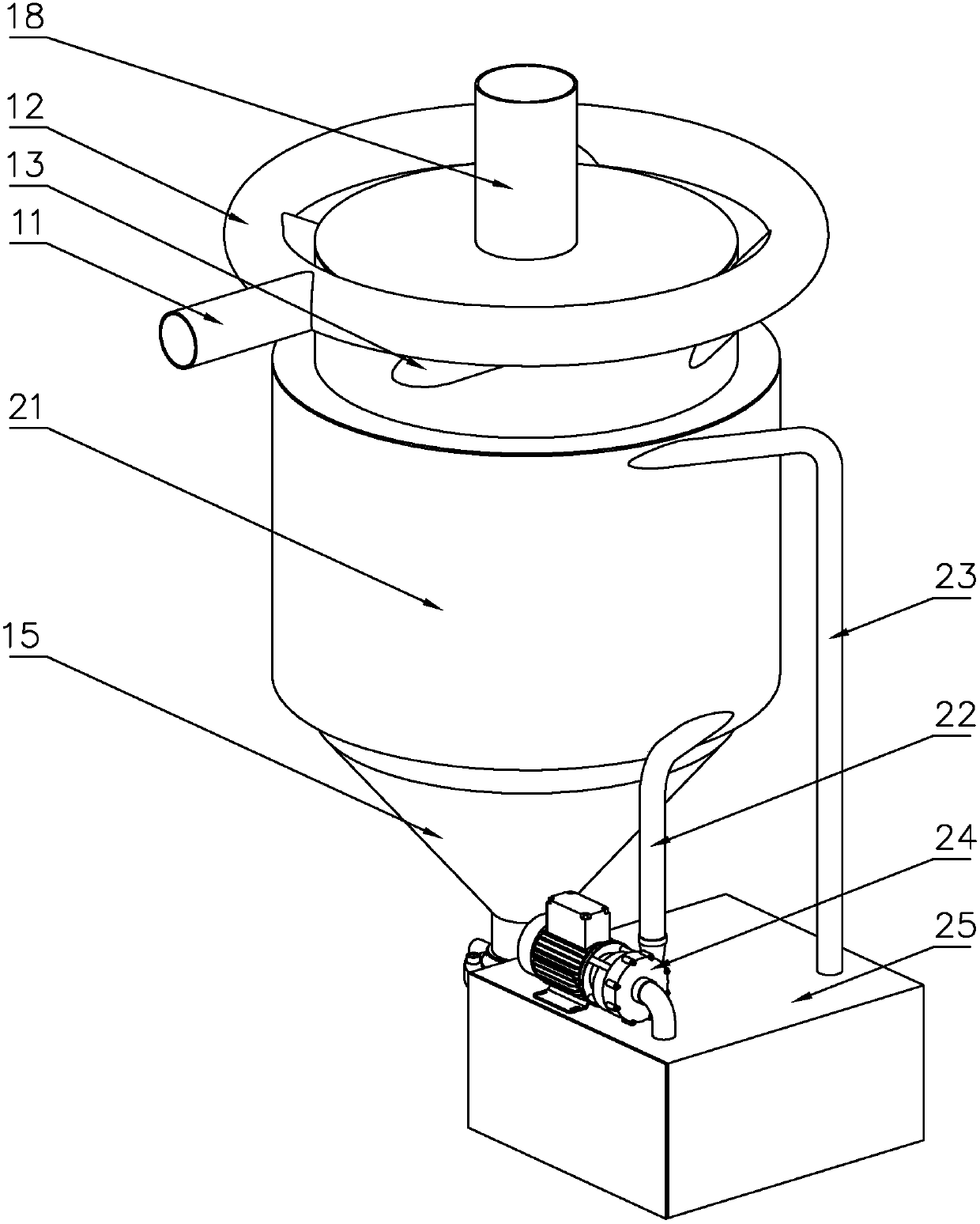
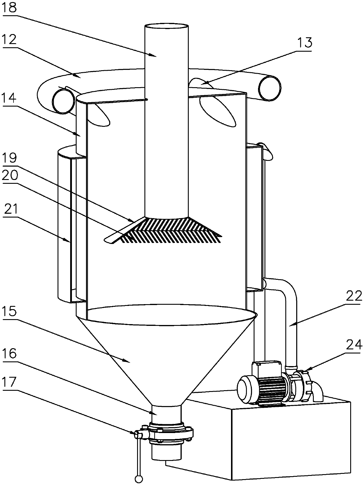
[0015] For the convenience of those skilled in the art to understand, the following in conjunction with the attached Figure 1-2 , to further specifically describe the technical solution of the present invention.

[0016] A gas-liquid separator for gas treatment, comprising an air inlet main pipe 11, a ring pipe 12, an air inlet branch pipe 13, a cyclone 14, a liquid collecting bucket 15, an air outlet pipe 18, a cooling water tank 21, a circulating water pump 24, and a water storage tank 25 One side of the upper part of the cyclone 14 is provided with some air inlet branches 13, the air inlet branches 13 are obliquely connected to the cyclone 14 at a certain angle, and the inclination angle between the air inlet branches 13 and the cyclone 14 is 5°. °-15°, the inclined air inlet branch pipe 13 speeds up the flow velocity of the mixed gas in the cyclone, and the air intake of multiple groups of air inlet branch pipes 13 has a certain driving effect on the air flow, improving t...


PUM


Abstract

The invention discloses a gas-liquid separator for gas treatment, which comprises a main air inlet pipe, a ring pipe, an air inlet branch pipe, a cyclone, a cooling water tank, a circulating water pump, and a water storage pool. Several air inlet branch pipes are arranged on the upper side of the cyclone ;Several groups of intake branch pipes are connected through ring pipes, and one side of the ring pipes is provided with an intake main pipe; a liquid collecting bucket is provided on the lower side of the cyclone; There is a water inlet pipe on the lower side of the water tank. One end of the water inlet pipe is connected tangentially to the cooling water tank, and the water inlet direction is opposite to the direction of the cyclone. The other end is connected to the circulating water pump. There is a water outlet pipe on the upper side of the cooling water tank. The water tank is connected tangentially, and the other end is inserted into the interior of the water storage tank. In the present invention, a plurality of groups of tangential intake branch pipes are arranged on the cyclone to divide the flow and remove liquid, and a cooling water tank is arranged on the outer wall of the cyclone, and the water inlet direction is opposite to the direction of the cyclone, which enhances the condensation effect of the liquid droplets and thereby enhances the cooling effect of the cyclone. Gas-liquid separation effect.

Description

technical field [0001] The invention belongs to the technical field of environmental protection equipment, in particular to a gas-liquid separator for gas treatment. Background technique [0002] Gas-liquid separation technology is a technology that separates mist or liquid droplets from a gas flow. This technology is widely used in petroleum, chemical industry (such as the purification and separation of raw material gas in the production of synthetic ammonia, nitric acid and methanol, and the desulfurization of circulating hydrogen for repeated use in hydrogenation units), natural gas exploitation, storage, transportation and deep processing, recovery of diesel hydrogenation tail gas, Wet desulfurization, flue gas waste heat utilization, wet dust removal and fermentation engineering processes are used to separate and remove harmful substances or efficiently recover useful substances; in the past gas-liquid separation process, the gas-liquid separation effect is poor, and th...

Claims


Application Information

Patent Timeline
IPC IPC(8): B01D53/24B01D53/26
CPCB01D53/24B01D53/265
Inventor 胡炳涛
Owner 邹德学
Why Eureka
Try Eureka