Micro fluid control equipment used for biochemical detection

A biochemical detection and microfluidic technology, applied in the field of microfluidics, can solve the problems of affecting the detection effect and insufficient contact of the reaction fluid, and achieve the effects of good reproducibility, thorough reaction, and full contact and mixing.

Active Publication Date: 2018-02-27
TAIZHOU BOYING BIOTECHNOLOGY CO LTD
View PDF6 Cites 10 Cited by
  • Summary
  • Abstract
  • Description
  • Claims
  • Application Information

AI Technical Summary

Problems solved by technology

[0003] Most of the existing microfluidic chips are immobilized biomolecules on the carrier (such as substrate, membrane, etc.) as t

Method used


Image

  • Micro fluid control equipment used for biochemical detection
  • Micro fluid control equipment used for biochemical detection
  • Micro fluid control equipment used for biochemical detection

Examples


Example Embodiment

[0030] Example 1

[0031] This embodiment specifically illustrates the structure of the microfluidic device of the present invention.

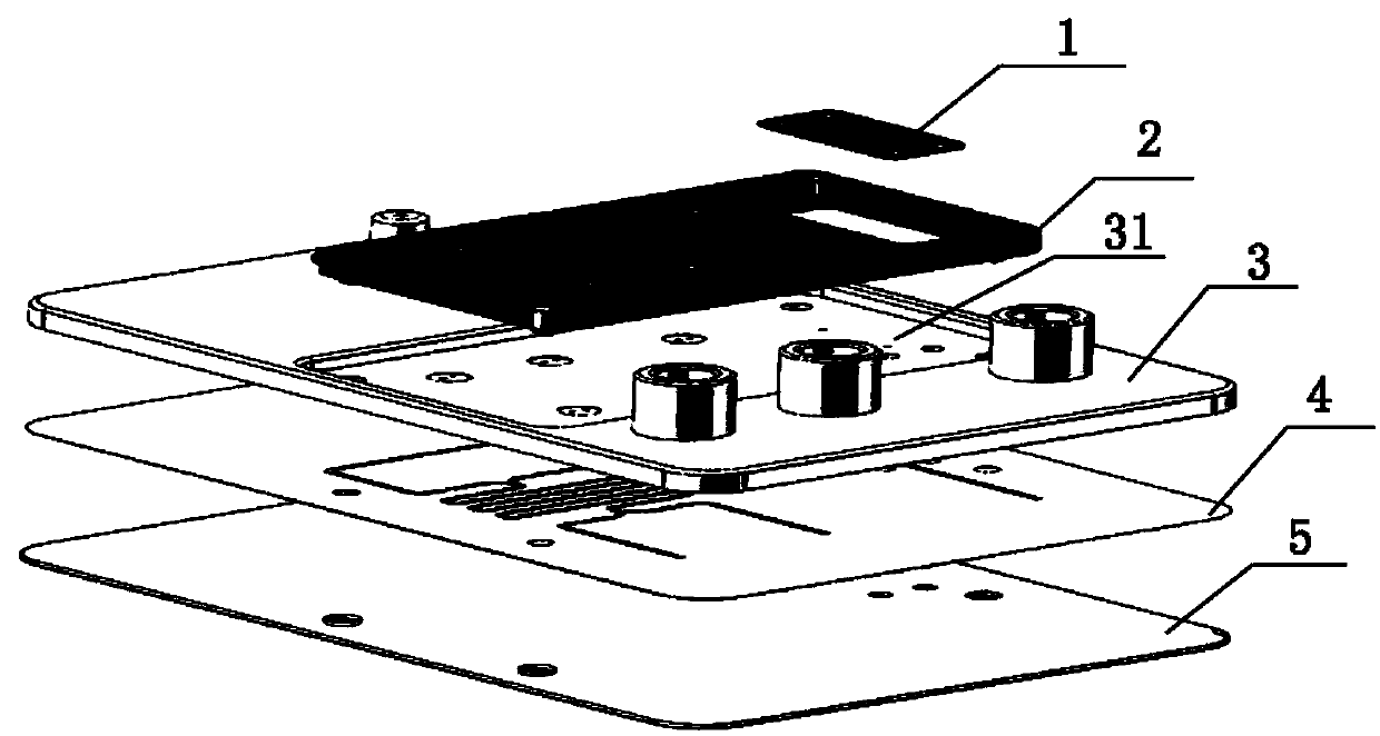
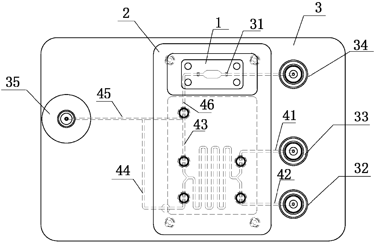
[0032] Such as Figure 1-3 As shown, the microfluidic device of the present invention includes a fluid channel chip and a detection area 1; the fluid channel chip is used for fluid sampling and mixing, and the fluid channel chip is provided with first micropores 31; The detection liquid enters the detection area 1 through the first microhole 31 for detection.

[0033] Such as Figure 1-3 As shown, the detection area structure in this embodiment includes two detection units.

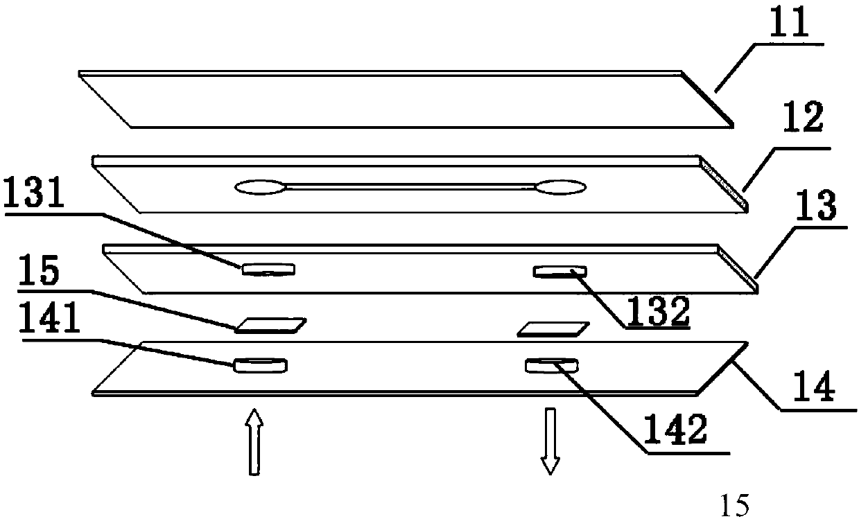
[0034] image 3 It is a schematic diagram of the structure of the detection area including two detection units. The structure of the detection area includes a cover sheet 11, a first substrate 12, a second substrate 13, and a third substrate 14 from top to bottom; The side of a substrate 12 provided with micro-channels is bonded to a side of the second substrate 13; the second s...

Example Embodiment

[0041] Example 2

[0042] The difference between this embodiment and Embodiment 1 is only that the detection area includes at least 3 detection units, and multiple detection units are connected in series or in parallel.

[0043] Such as Figure 4 As shown, Figure 4 (a) is the structure of the detection zone in series, the mixed fluid to be detected enters the first detection unit through the first micropore, then passes through the second...n-1th detection unit in turn, and finally passes through The micropore of the nth detection unit returns to the fluid channel chip and enters the waste liquid pool to complete the detection;

[0044] Figure 4 (b) It is a detection zone structure in which the multiple detection units are connected in parallel. A micro channel is also provided on the lower surface of the third substrate. After the mixed fluid to be detected passes through the first micropore, the Divide on the micro flow channel and enter the first n-1 detection units respectivel...

Example Embodiment

[0045] Example 3

[0046] This example illustrates the preparation method of the detection zone 1 described in Example 1. The steps are as follows:

[0047] (1) Using conventional technology, micro-channels are provided on one side of the first substrate; micro-holes are provided on the second substrate and the third substrate;

[0048] (2) Fix biomolecules on a large-area membrane, and then cut the large-area membrane into membrane units with biomolecules immobilized as a biomolecule coating;

[0049] (3) The cover sheet, the first substrate, the second substrate and the third substrate are sequentially bonded from bottom to top, and the biomolecule coating film is fixed between the second substrate and the third substrate in an embedded form, Then assembled and fixed to the control layer.


PUM


Abstract

The invention relates to micro fluid control equipment used for biochemical detection. The equipment comprises a fluid flow passage chip and a detection area, wherein the fluid flow passage chip is used for fluid sample introduction and mixing, and first micropores are formed in the fluid flow passage chip; mixed liquid to be detected enters into the detection area through the first micropores fordetection; the detection area structurally comprises a cover plate, a first substrate, a second substrate and a third substrate in sequence from top to bottom; the cover plate, the first substrate, the second substrate and the third substrate are bonded in sequence, micropores for a fluid to come in and out are formed in the cover plate, the first substrate, the second substrate and the third substrate, and biomolecular films are fixed among the micropores in the second substrate and the third substrate; and the mixed fluid to be detected passes through the first micropores, third micropores,the biomolecular films, second micropores and a first substrate micro-channel fluid inlet in sequence to enter into a first substrate micro-channel for reaction. According to the micro fluid controlequipment disclosed by the invention, the detection area is independent of micro-channels, and the fluid is smooth after running through the biomolecular films, so that sufficient contact and reactionof the fluid and the biomolecular films are realized.

Description

technical field [0001] The invention relates to the field of microfluidic technology, in particular to a microfluidic device for biochemical detection. Background technique [0002] Microfluidic chip is an important science and technology of this century. Microfluidic chip is a system that manipulates the flow of microscale fluids in tiny channels or structures. It can be integrated on a sheet as small as a few square centimeters. A biology or chemistry laboratory. Microfluidic chips can greatly reduce sample consumption, that is, greatly reduce costs, reduce sample processing time, and improve detection resolution / sensitivity, which has a profound impact and significance on the development of modern technology. Microfluidic chips can be applied in a wide range of fields, and are currently involved in disease diagnosis, drug screening, environmental testing, food safety and other fields. [0003] Most of the existing microfluidic chips are immobilized biomolecules on the c...

Claims


Application Information

Patent Timeline
IPC IPC(8): B01L3/00G01N33/53
CPCB01L3/5027B01L3/50273B01L3/502738B01L2200/10B01L2300/0861B01L2300/0887B01L2300/12B01L2300/16B01L2400/0487G01N33/5302
Inventor 葛瑞金杨昕阎玉川张继超
Owner TAIZHOU BOYING BIOTECHNOLOGY CO LTD
Why Eureka
Try Eureka