Dual-wavelength phase-shift interference aspheric surface measurement method and device based on partial compensation method

A technology of phase-shift interference and measurement method, which is applied in the field of high-precision measurement of optical aspheric surface error, can solve the problems of increasing the difficulty and cycle of instrument design, shorten the cycle of instrument design, reduce the difficulty and cost of system design, and achieve high The effect of precision reconstruction

Active Publication Date: 2018-03-06
BEIJING INSTITUTE OF TECHNOLOGYGY
View PDF12 Cites 17 Cited by
  • Summary
  • Abstract
  • Description
  • Claims
  • Application Information

AI Technical Summary

Problems solved by technology

For the application of TWPSI to the measurement of steep aspheric surfaces, the chromatic aberration of the compensation mirror and interferometer has always been the key problem to be sol

Method used


Image

  • Dual-wavelength phase-shift interference aspheric surface measurement method and device based on partial compensation method
  • Dual-wavelength phase-shift interference aspheric surface measurement method and device based on partial compensation method
  • Dual-wavelength phase-shift interference aspheric surface measurement method and device based on partial compensation method

Examples


Example Embodiment

[0064] Example 1: Measurement of large asphericity ellipsoid surface.

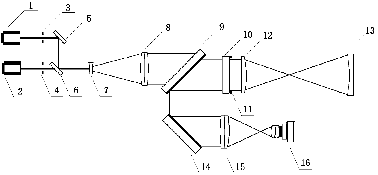
[0065] The implementation device of this embodiment is as figure 2 As shown, the working wavelength λ output by the first laser (1) and the second laser (2) 1 And λ 2 Respectively 532nm and 556nm, the resulting equivalent synthetic wavelength λ eq It is 12.325μm, and the maximum measurable difference between adjacent optical path differences is 6.162μm.

[0066] In this embodiment, the transparent aperture D of the tested ellipsoidal surface (13) is 580mm, and the curvature radius of the aspheric surface is R 0 It is -1179.447mm, the relative diameter of aspheric surface is D / R 0 The maximum asphericity of the tested ellipsoid relative to the vertex sphere and the best reference sphere is 281.85μm and 67.80μm, respectively, which is a fairly large aspherical surface. This embodiment is in large aspherical surface The additional facet error of the ellipsoid produces a steep wavefront.

[0067] The glass material ...

Example Embodiment

[0079] Example 2: Parabolic measurement with large surface error.

[0080] In this embodiment, the tested aspheric surface (13) is a parabolic surface with large surface error, its clear aperture D is 108mm, and the vertex radius of curvature R 0 -1727.2mm, the relative diameter of the paraboloid is D / R 0 1 / 16, the maximum asphericity of the tested parabola relative to the vertex sphere and the best reference sphere are 0.206μm and 0.052μm, respectively, which is a shallow aspheric surface.

[0081] The glass material of the partial compensation mirror (12) designed to compensate for the parabola is K9, and the curvature radius of the front and rear surfaces is r 1 And r 2 They are 760mm and -4965mm respectively, which are also a simple double convex lens. The thickness of the partial compensation mirror (12) is 20mm, and the distance between the partial compensation mirror (12) and the measured aspheric surface (13) is 2985mm.
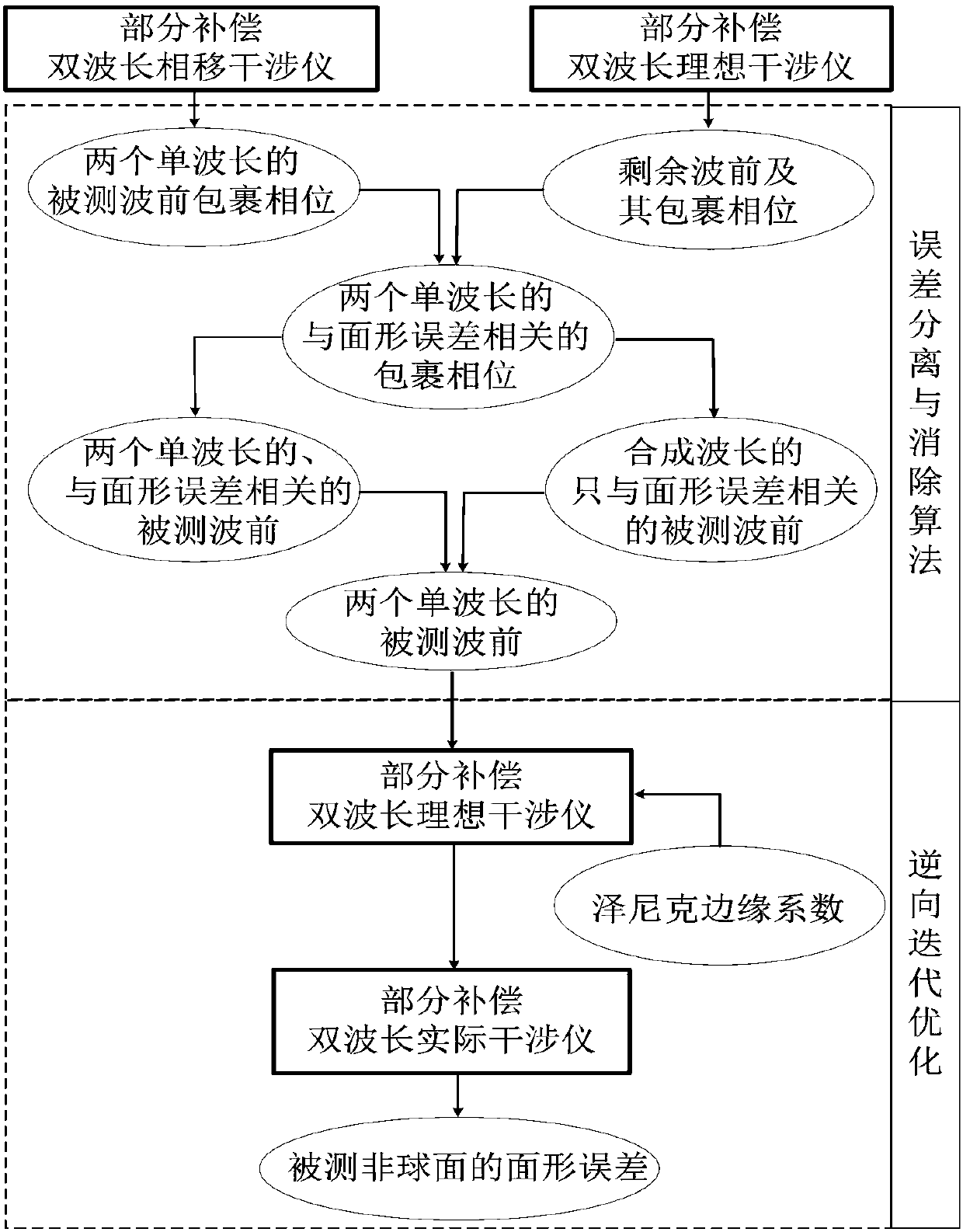
[0082] Using the method proposed by the present inventi...


PUM

PropertyMeasurementUnit
Clear apertureaaaaaaaaaa
Thicknessaaaaaaaaaa
Clear apertureaaaaaaaaaa

Abstract

The invention belongs to the technical field of optical precision testing, and relates to a dual-wavelength phase-shift interference method based on a partial compensation method and an implementationdevice. The method comprises the steps of building a partial compensation method dual-wavelength phase-shift interferometer, and acquiring measured wavefront wrapped phases of two single wavelengths;modeling a partial compensation method dual-wavelength ideal interferometer, and acquiring residual wavefronts and wrapped phases of the two single wavelengths; eliminating known and unknown wavefront variations in the measured wavefront wrapped phases by adopting an error separation and elimination algorithm, and finally optimizing and reconstructing surface-shape error of the measured asphericsurface by adopting reverse iteration. The device comprises a first laser, a second laser, a first slit, a second slit, a first plane mirror, a second plane mirror, a first beam splitter, a second beam splitter, a beam expander, a collimating mirror, a standard plane mirror, a phase shifter, a partial compensating mirror, a measured aspheric surface, an imaging lens and an interferogram acquisition assembly containing a sparse array sensor. The method and device provided by the invention are particularly applicable to processing quality measurement for gradient aspheric surfaces with a small surface-shape error, molded aspheric surfaces with a great surface-shape error and free curved surfaces.

Description

technical field [0001] The invention belongs to the technical field of optical precision testing, and in particular relates to the improvement of a dual-wavelength phase-shifting interference detection method, which is used to realize high-precision measurement of optical aspheric surface shape errors with large asphericity or large surface shape errors. Background technique [0002] Replacing the traditional spherical surface with an aspheric surface can improve the imaging performance of the system with fewer optical elements, and at the same time has the advantages of increasing the degree of design freedom, reducing the volume and reducing the weight of the system. In precision optical systems such as aerospace cameras and astronomical telescopes, the manufacture and testing of certain aspheric surfaces, especially steep optical aspheric surfaces, even play a decisive role in the upgrading of optical systems. However, the high-precision detection of aspheric wavefronts, ...

Claims


Application Information

Patent Timeline
IPC IPC(8): G01B11/24
Inventor 郝群张丽琼胡摇王劭溥李腾飞
Owner BEIJING INSTITUTE OF TECHNOLOGYGY
Why Eureka
Try Eureka