
Shaft furnace reduction system with distribution and purge functions

A gas-based shaft furnace and shaft furnace technology, which is applied in the field of metallurgy, can solve the problems of inconvenient temperature and gas composition control, fine-grained ore powder easily escaping gas utilization, and low reduction efficiency.

Pending Publication Date: 2018-03-09
JIANGSU PROVINCE METALLURGICAL DESIGN INST
View PDF0 Cites 0 Cited by
  • Summary
  • Abstract
  • Description
  • Claims
  • Application Information

AI Technical Summary

Problems solved by technology

In order to ensure the quality of direct reduced iron products, the direct reduction process has extremely strict requirements on iron-containing raw materials, especially iron ore pellets that are directly fed into the furnace. properties, and the ore is generally set in a stacked state in the shaft furnace, because the diffusion of gas in the stacked ore is slow, it takes about 6 hours for full reduction, and the reduction and cooling are all carried out in the furnace body, further prolonging the process Time will also cause inconvenience in controlling the temperature and gas composition in the furnace
The existing gas-based shaft furnace only relies on the heat brought in by the reducing gas as the heat source. The actual reduction temperature is around 800-920°C, and it is difficult to further increase the reduction temperature, which directly limits the reduction rate of the pellets, which is the main reason for the long reduction time. one of the limiting factors
[0004] The current fluidized bed process is commonly used as the Fior flow state method, which uses mineral materials in the range of 0.25~4mm, and the mineral materials are suspended in the fluidized bed, which increases the area in contact with the reducing gas. Coarse, the reduction time can only be reduced to a certain extent. At the same time, the fine-grained ore powder is easy to escape and the gas utilization rate is low. To solve these problems, generally multiple fluidized beds are used in series to increase the contact time between the ore and the reducing gas. to improve gas utilization, which complicates the process
[0005] In the various process systems mentioned above, in order to make the reducing gas meet the use requirements, multiple gas heating and cooling devices need to be installed, which not only increases the equipment investment, but also makes the process system complicated
[0006] It can be seen that the current direct reduction ironmaking technology generally has problems such as low reduction efficiency and complicated process equipment. Therefore, there is an urgent need for a method and system that has high reduction efficiency, simple process, and is conducive to improving the metallization rate.

Method used


Image

  • Shaft furnace reduction system with distribution and purge functions
  • Shaft furnace reduction system with distribution and purge functions
  • Shaft furnace reduction system with distribution and purge functions

Examples


Embodiment 1

[0059] 1) Transport the mineral powder to the silo, and send the mineral powder in the silo to the preheating silo for preheating; wherein the particle size of the mineral powder is 100 mesh, accounting for more than 80%;

[0060] 2) The preheated ore powder is sent to the gas-based shaft furnace, and the driving device outside the shaft furnace is started to control the driving roller to drive the chain and hopper to move;

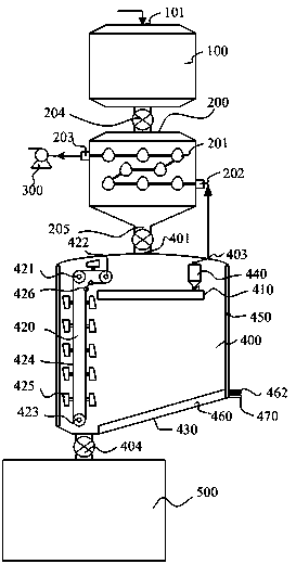
[0061] 3) The mineral powder falls through the distributor, and the reducing gas is sprayed upward from the vertical upward hole of the gas distribution device, which generates resistance to the mineral powder that moves downward by gravity, and the falling mineral powder and the rising The reducing gas undergoes a reduction reaction to generate incompletely metallized materials, which are collected to the lower part of the circulating feeding device through the guide trough through the purging device, and part of the metallized materials are transferred to the...

Embodiment 2

[0064] 1) Transport the ore powder to the silo, and send the ore powder in the silo to the preheating silo for preheating; wherein the particle size of the ore powder is 100 mesh, accounting for more than 90%;

[0065] 2) The preheated ore powder is sent to the gas-based shaft furnace, and the drive device outside the shaft furnace is started to control the drive roller to drive the chain and hopper to move;

[0066] 3) The mineral powder falls through the distributor, and the reducing gas is sprayed upward from the vertical upward hole of the gas distribution device, which generates resistance to the mineral powder that moves downward by gravity, and the falling mineral powder and the rising The reducing gas undergoes a reduction reaction to generate incompletely metallized materials, which are collected to the lower part of the circulating feeding device through the guide trough through the purging device, and part of the metallized materials are transferred to the cloth by the ho...


PUM


Abstract

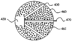
The invention relates to a shaft furnace reduction system with functions of gas distribution and purging, which includes a feed bin, a preheating bin, a gas-based shaft furnace and a melting furnace. The shaft furnace is connected, and the gas-based shaft furnace is connected to the melting furnace. The gas outlet holes of the reducing gas distribution device of the present invention are vertically upward and evenly distributed, which can increase the falling resistance of the materials in the furnace, prolong the falling time, and single-shot The reduction time is extended, the temperature is more uniform, and the metallization rate is higher. The two sides of the reducing gas distribution device are enough to form a guide groove, so that the material can quickly gather into the guide groove; the guide groove purging device can make the material in the feed groove Quickly converge to the lower part of the material circulation system, connect to the reducing gas pipeline of the purging device, install a reducing gas regulating valve, and adjust the opening of the regulating valve to control the amount of reducing gas entering the purging device pipeline, thereby reducing the amount of guide tank The accumulation and residence time of materials in the machine can be shortened, and the material circulation speed can be accelerated.

Description

Technical field [0001] The invention belongs to the technical field of metallurgy, and specifically relates to a shaft furnace reduction system with gas distribution and purging functions. Background technique [0002] The process of producing direct reduced iron is called the direct reduction method, which belongs to the non-blast furnace ironmaking process and is divided into two categories: gas-based method and coal-based method. Gas-based methods mainly include Midrex, HYL, PERED, fluidized bed, and coal-based methods are mainly rotary kiln and rotary hearth furnace methods. About 80% of direct reduced iron is produced by gas-based methods, mainly MIDREX and HYL methods. [0003] Gas-based direct reduction technology has been widely used in natural gas-rich areas. In recent years, with the development and utilization of coal-based gas as a reducing agent technology, gas-based shaft furnace direct reduction technology has attracted widespread attention in my country. In order ...

Claims


Application Information

Patent Timeline
IPC IPC(8): C21B13/02C21B13/14
CPCC21B13/02C21B13/0006C21B13/0073C21B13/14
Inventor 吴道洪冯鲁兴邓君韩志彪唐敬坤曹志成温雨馨
Owner JIANGSU PROVINCE METALLURGICAL DESIGN INST
Learn More