Denitrification system and denitrification method for gas turbine

A gas turbine and denitrification technology, which is applied in the field of flue gas denitrification, can solve the problems of low temperature and ineffective work, and achieve the effect of promoting denitrification reaction, improving efficiency and improving denitrification efficiency

Active Publication Date: 2018-03-13
TSINGHUA UNIV
View PDF11 Cites 6 Cited by
  • Summary
  • Abstract
  • Description
  • Claims
  • Application Information

AI Technical Summary

Problems solved by technology

For example, in recent years, the European Union has begun to limit the NO x Emissions, the SCR aftertreatment device is too cold to work effectively during the start-up phase of the gas turbine

Method used


Image

  • Denitrification system and denitrification method for gas turbine
  • Denitrification system and denitrification method for gas turbine
  • Denitrification system and denitrification method for gas turbine

Examples


Embodiment Construction

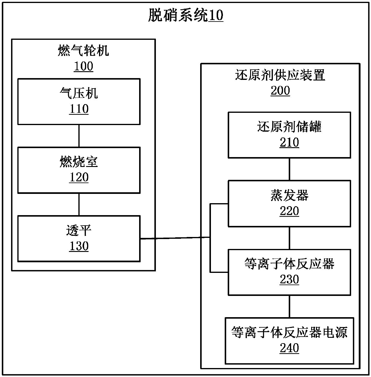
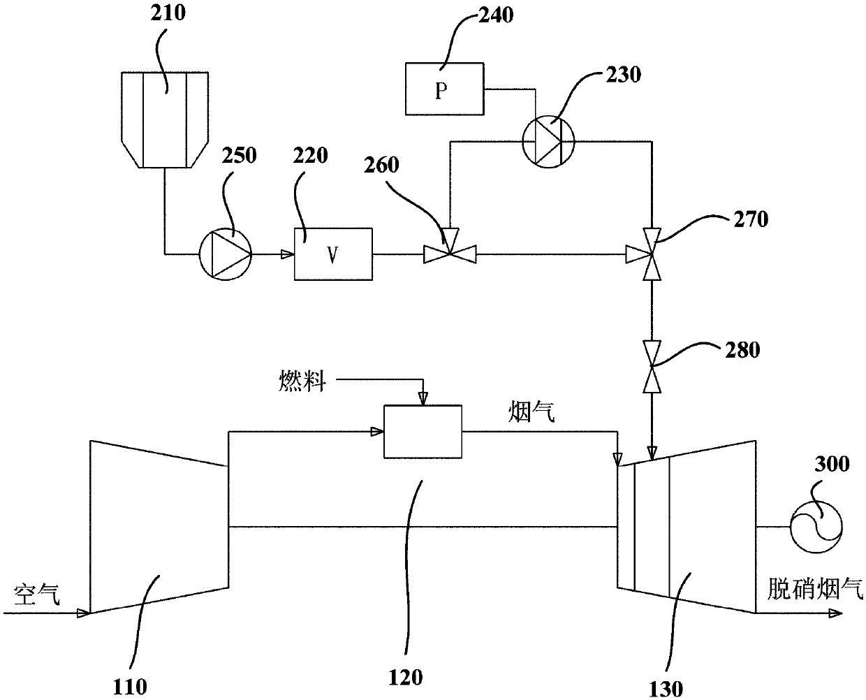
[0026] figure 1 is a schematic structural diagram of a denitrification system according to an embodiment of the present invention. This denitrification system 10 includes a gas turbine 100, as known to those skilled in the art, the gas turbine 100 includes: a gas turbine compressor 110, which continuously sucks in air from the atmosphere and compresses it; The air mixed combustion; the gas turbine turbine 130 converts the energy generated by the fuel combustion in the gas turbine combustor 120 into mechanical energy, and the flue gas generated after converting the energy of the fuel into mechanical energy contains nitrogen oxides. Generally, a generator 300 is connected after the gas turbine turbine 130 to convert mechanical energy into electrical energy for output.

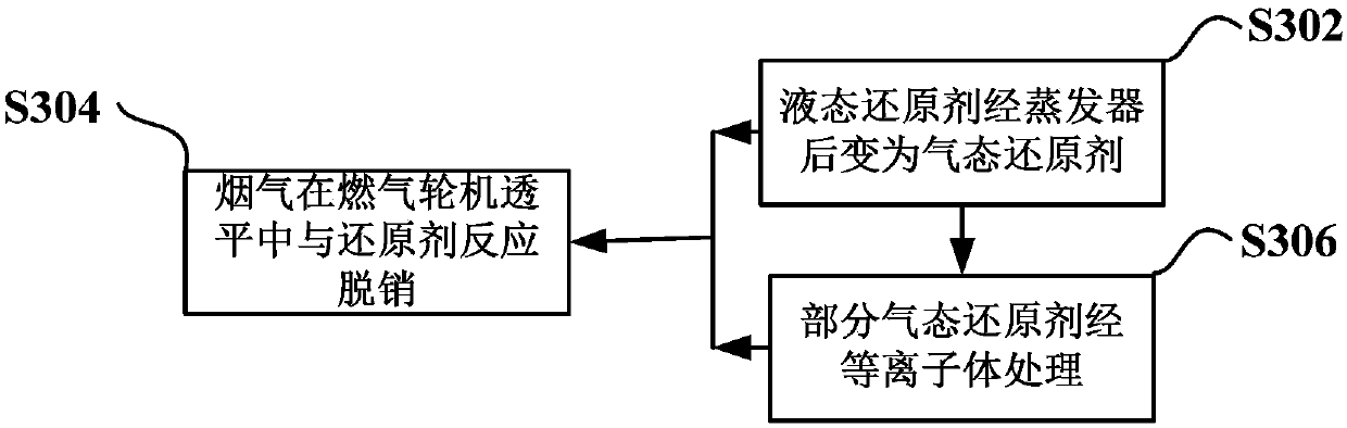
[0027] In some embodiments, the denitrification system 10 of the present invention further includes a reducing agent supply device 200, which is used to provide a denitration reducing agent for reducing nitrogen...


PUM


Abstract

The invention provides a denitrification system and a denitrification method for a gas turbine. The denitrification system comprises the gas turbine and a reducing agent supplying system. A denitrification reducing agent is provided for a turbine by using a reducing agent output pipeline communicated to the rear part of a first-stage moving blade of the turbine of the gas turbine; nitric oxide influe gas, exhausted from a combustion chamber of the gas turbine, is contact with the denitrification reducing agent in the turbine of the gas turbine to carry out selective non-catalytic reduction reaction, and denitrification of the flue gas is finished, wherein before the reducing agent enters the turbine for reacting, more free radicals can be generated by plasma treatment and facilitate a denitrification reaction. By using the technical scheme provided by the invention, denitrification is realized in the turbine of the gas turbine, and high pressure and high rotating speed of the turbineof the gas turbine are sufficiently utilized, so that the mixing of the reducing agent and the flue gas is benefited, the denitrification reaction is promoted, and the denitrification efficiency is improved; besides, post treatment equipment also can be reduced, so that the complexity of the system and investment expenses of equipment are reduced.

Description

technical field [0001] The invention relates to a flue gas denitrification method, in particular to a gas turbine denitrification system and method. Background technique [0002] The combined cycle power generation with gas turbine as the core is an advanced power generation method, which has the characteristics of high efficiency, fast start and stop, and lower pollutants than coal-fired power plants, and plays an important role in energy conservation and emission reduction. The development trend of modern gas turbines is to increase the turbine inlet temperature (combustion chamber outlet temperature) to improve efficiency. However, an increase in the outlet temperature of the combustion chamber will emit nitrogen oxides (NO x ) higher smoke. NO x As one of the main pollutants emitted by gas turbines, it can cause acid rain, photochemical pollution and smog, and endanger human health. [0003] At present, there are two main methods of post-treatment of flue gas in ther...

Claims


Application Information

Patent Timeline
Patent Type & Authority Applications(China)
IPC IPC(8): B01D53/94B01D53/56F02C6/00
Inventor 刘昊杨李苏辉
Owner TSINGHUA UNIV
Why Eureka
Try Eureka