LED lamp

A technology for LED lamps and light sources, which is applied to cooling/heating devices of lighting devices, lighting and heating equipment, semiconductor devices of light-emitting elements, etc. Production cost, the effect of ensuring normal operation

Pending Publication Date: 2018-03-16
厦门吉来特光电有限公司
View PDF5 Cites 1 Cited by
  • Summary
  • Abstract
  • Description
  • Claims
  • Application Information

AI Technical Summary

Problems solved by technology

[0004] 1. The light source is basically a distributed light source, which usually includes a number of LED grains arranged in a matrix array or a starry sky, or arranged at intervals along several concentric circles. Philips EMC plastic bracket 3030 lamp beads, each one watt, hundreds of 100 watts; the disadvantage is that the distribution of multiple LED crystal grains is too wide, too many light-emitting positions are different and discontinuous, resulting in the water chestnut of the illuminated object The diamond lines and lines are not obvious and fuzzy. The most important thing is that the shadows produced are too much and too messy, which is not suitable for commercial lighting.
[0005] 2. Existing heat sinks generally consist of a heat conduction plate and heat dissipation fins, wherein the heat conduction plate is responsible for conducting the heat in the LED grain first, and the heat dissipation fins are connected to the heat conduction plate for heat transfer to dissipate the heat into the atmosphere In the past, most of the contact between the heat conduction plate and the heat dissipation fins adopts a touch contact method, that is, the two plates are pressed against each other. Due to actual production and processing, the two plates will not be completely flat due to factors such as tolerances. , so the above-mentioned touch type is actually a combination of several contact points and connected by air, its heat conduction and heat dissipation efficiency are low, and it can be barely used for some distributed light sources that do not require high heat dissipation efficiency, but It cannot be applied to concentrated light sources
[0006] 3. The above-mentioned LED lamps generally use a reflector cup to adjust the light emitted by the light source. In order to meet some specific illumination parameter requirements, the reflector cup needs to be set very long, causing the entire LED lamp to have The disadvantage of large volume; in order to solve these problems, there are also factories that package and form a lens outside each LED grain, and then use the lens to integrate the light. However, since each LED grain needs to be equipped with a lens, not only The processing procedure and cost are greatly increased, and because the light is not uniformly designed for the optical path, it still has the disadvantage of poor light effect

Method used


Image

  • LED lamp
  • LED lamp
  • LED lamp

Examples


Embodiment approach 1

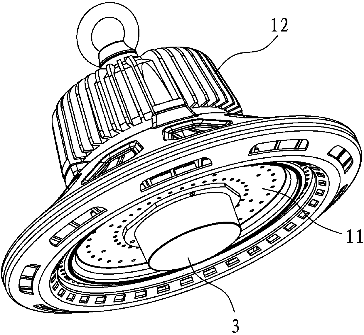
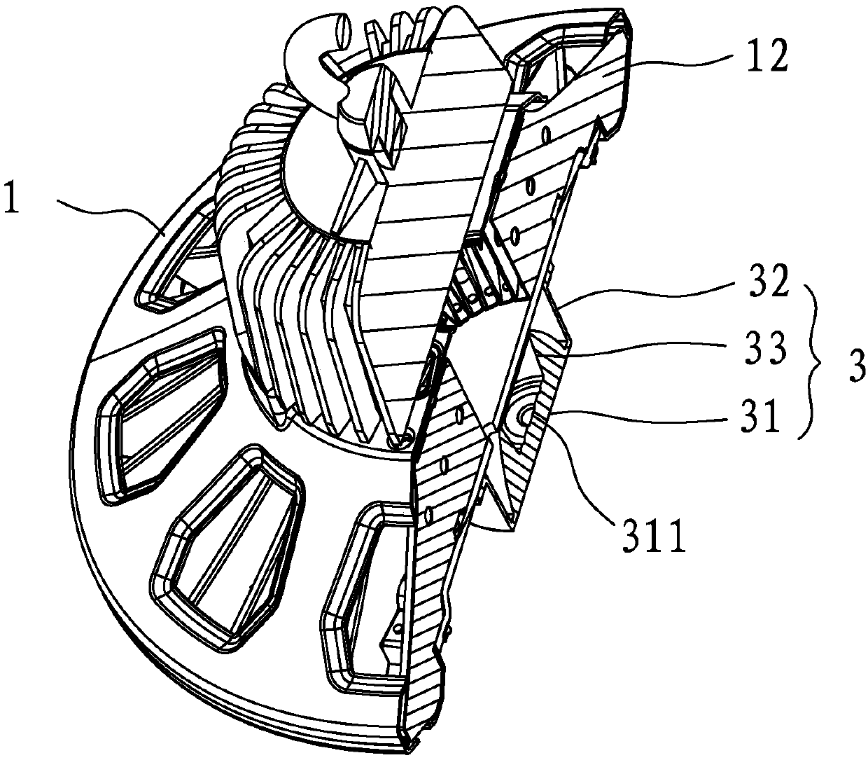
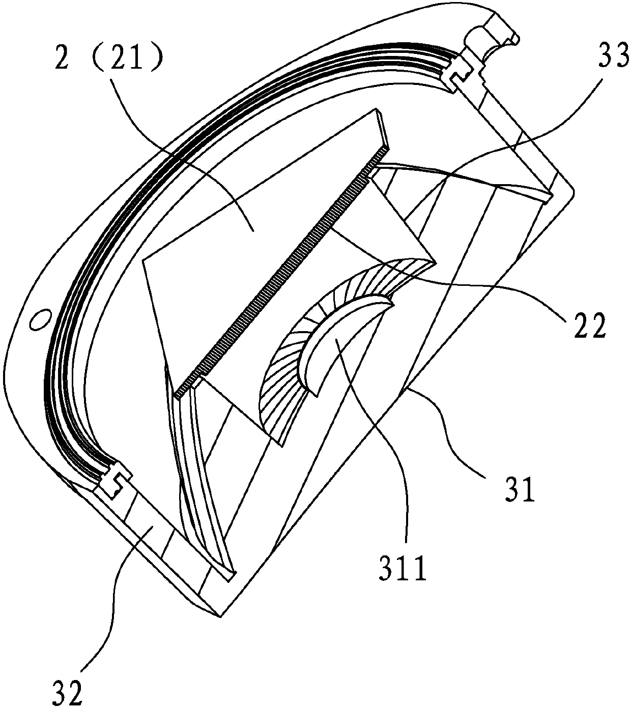
[0049] The radiator 1 has a heat conduction plate 11 and several heat dissipation fins 12 connected to the heat conduction plate 11, and the heat conduction plate 11 and the plurality of heat dissipation fins 12 are connected by riveting. In this way, compared with the direct contact between the heat conducting plate 11 and the main body of the heat sink 12 in the traditional technology, the contact area between each other is greatly increased by riveting, and the heat dissipation performance is improved.

Embodiment approach 2

[0051] The heat sink 1 has a heat conduction plate 11 and several heat sinks 12 connected to the heat conduction plate 11. A nickel-plated layer is also formed on the heat conduction plate 11. The heat conduction plate 11 passes through the nickel-plated layer and the solder layer in turn. It is connected with several heat sinks 12 by welding. By soldering after nickel plating, the contact area between the heat conducting plate 11 and the main body of the heat sink 12 is greatly increased, thereby greatly improving the heat dissipation efficiency.

Embodiment approach 3

[0053] The heat sink 1 has an integrated heat sink 12 formed by cold forging process and a heat conduction bottom plate, and a nickel plating layer is also formed on the heat conduction bottom plate. Such direct one-piece molding improves heat dissipation efficiency and ensures work efficiency.

[0054] In this way, the present invention can greatly improve the integrity of the entire heat conduction channel by forming a nickel-plated layer and then cooperating with solder, and solves the disadvantage that aluminum materials cannot be soldered by means of nickel plating, thereby greatly improving the heat conduction and thermal conductivity of the entire LED lamp. The heat dissipation performance ensures that the entire LED lamp can work normally.


PUM


Abstract

The invention discloses an LED lamp. The LED lamp comprises a power source, a radiator, a light source and a light guiding assembly; the light source is a concentrated light source which is provided with a substrate and a plurality of CSP crystal grains formed on the substrate in a concentrated mode; the substrate is provided with a conductive layer, a nanometer ceramic insulating coating layer and an aluminum layer which are sequentially arranged from surface to inside; the CSP crystal grains are welded on the conductive layer, and heat of the CSP crystal grains is conducted out into the radiator by the nanometer ceramic insulating coating layer and the aluminum layer; the light guiding assembly comprises a total-reflection lens arranged on the periphery of the concentrated light source in a covering mode and a lens located on the front portion of the light emitting direction of the concentrated light source; and one part of light emitted by the concentrated light source is directly irradiated onto the lens, and the other part of the light emitted by the concentrated light source is reflected by the total-reflection lens and then irradiated onto the lens. Compared with the prior art, the LED lamp has the characteristics of being low in cost, compact in structure and good in waterproof effect and dustproof effect.

Description

technical field [0001] The invention relates to the field of LED lamps, in particular to an LED lamp with good heat dissipation effect, low cost and good light uniformity. Background technique [0002] LED lamps on the market can be divided into many varieties based on their different application places. As a common product in LED lamps, patio lights and high bay lights are generally composed of a power supply, a radiator, a light source, and a reflector. The light source is a component used to emit light, and the power supply provides energy for the light source. The radiator is used to quickly dissipate the heat emitted by the light source, and the reflector cup is used to adjust the light emitted by the light source to ensure that the light emitted by the light source can be irradiated as required to meet people's lighting needs. [0003] However, the above-mentioned existing sky lights and high bay lights usually have the following disadvantages: [0004] 1. The light ...

Claims


Application Information

Patent Timeline
Patent Type & Authority Applications(China)
IPC IPC(8): F21S8/06F21V5/04F21V7/04F21V29/76F21V29/87F21V31/00F21Y115/10
CPCF21S8/063F21V5/04F21V7/04F21V29/76F21V29/87F21V31/00F21Y2115/10
Inventor 欧阳伟张智丰黄泓豪欧阳成
Owner 厦门吉来特光电有限公司
Why Eureka
Try Eureka