A multi-band fluorescence loss method, multi-color super-resolution imaging method and device

A fluorescence loss, multi-band technology, applied in the field of optical microscopy, can solve the problems of difficult to achieve loss effect, failure to achieve light stability, high loss optical power, etc., to achieve long-term three-dimensional imaging, high-efficiency light The effect of controlling loss and reducing system cost

Active Publication Date: 2021-01-15
SOUTH CHINA NORMAL UNIVERSITY
View PDF3 Cites 0 Cited by
  • Summary
  • Abstract
  • Description
  • Claims
  • Application Information

AI Technical Summary

Problems solved by technology

[0003] But at present, the TPE-STED technology using traditional dyes still faces certain limitations and challenges in deep tissue super-resolution imaging, mainly reflected in: (1) The depleted laser is still located in the visible light band, and it scatters severely in biological tissues. It is difficult to achieve the ideal loss effect in larger depths
(2) The loss of optical power is large, which will cause serious thermal damage to biological tissues
(3) Commonly used STED fluorescent dyes generally have photobleaching or light flickering problems, which cannot achieve sufficient photostability and cannot meet the needs of long-term imaging
(4) The light source used in TPE-STED imaging is a high-power femtosecond light source, which is expensive and has a complex optical system, making it difficult to popularize
[0004] In order to overcome the above difficulties, the applicant has previously developed the STED microscopy technology based on rare earth doped up-conversion nanoparticles using continuous near-infrared laser excitation and loss, but at present this technology only realizes the super-resolution of a single type of nanoparticle Imaging, the amount of information obtained when applied to imaging is limited

Method used


Image

  • A multi-band fluorescence loss method, multi-color super-resolution imaging method and device
  • A multi-band fluorescence loss method, multi-color super-resolution imaging method and device
  • A multi-band fluorescence loss method, multi-color super-resolution imaging method and device

Examples


Embodiment 1

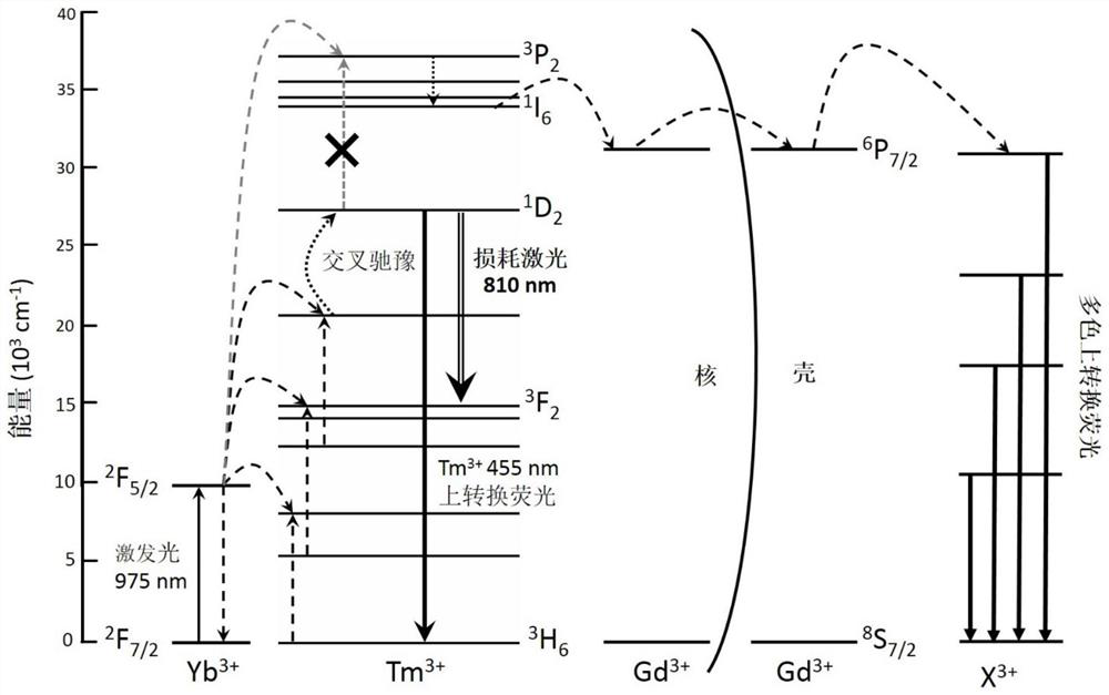
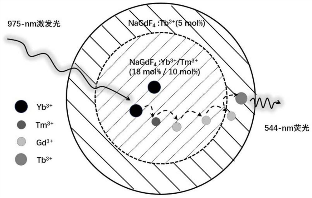
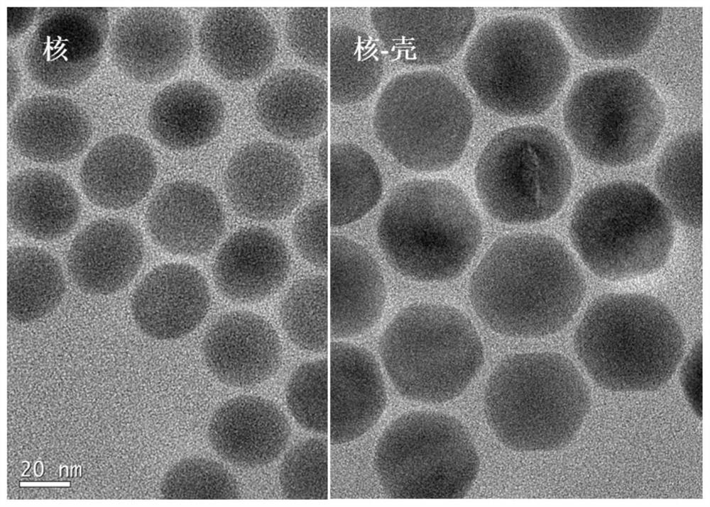
[0042] see figure 1 , figure 2 , image 3 , Figure 4 , Figure 5 , the fluorescent nanoparticles in this example use Tb 3+ As an activating ion, while achieving Tm 3+ 455nm, 475nm and Tb 3+ 490nm / 544nm / 585nm / 620nm and other multi-band up-conversion luminescence and loss. Schematic diagram of the core-shell upconversion nanoparticle structure figure 2 As shown, its core is NaGdF 4 As a matrix, doped with 18mol% Yb 3+ Ion and 10mol% Tm 3+ ion. NaGdF 4 as the matrix, doped with 5mol% Tb 3+ as an active ion. Migration ion Gd 3+ As the medium of energy transfer, transfer energy from accumulated ions Tm 3+ The high energy level is transferred to the activated ion Tb 3+ , emit 490nm / 544nm / 585nm / 620nm and other multi-band up-conversion fluorescence. Electron microscope images of nanoparticles synthesized by solvothermal method image 3 As shown, the core particle size is about 20 nanometers, and reaches 35 nanometers after wrapping the shell.

[0043] see Figur...

Embodiment 2

[0054] For the two-layer core-shell structure in Example 1, some active ions are due to the partial energy level and accumulated ion Tm 3+ Matching can easily cause cross energy transfer, resulting in reduced luminescence efficiency of activated ions. This embodiment provides a three-layer structure to avoid such cross energy transfer, see FIG. 9( a ). Compared with Example 1, this example adds a layer of undoped NaGdF between the core and the shell where the active ions are located. 4 As an isolation layer, see Figure 9(b) due to the Gd 3+ of 6 P 7 / 2 The energy level is higher than the excited state of the activated ion used, and the isolation layer can effectively prevent the excited state from the activated ion to the Tm 3+ The cross-transfer of intermediate energy levels improves the luminous efficiency of multi-wavelength fluorescence.

Embodiment 3

[0056] Based on the synthesis of multicolor fluorescent nanoparticles and the multiband fluorescence loss method in Example 1, this example provides a multicolor super-resolution imaging method.

[0057] The method includes the steps of:

[0058] In the same way, a continuous fiber-coupled laser with a wavelength of 975nm is used to emit a stable near-infrared wavelength laser as the excitation light. After the laser is collimated, a Gaussian solid beam is obtained;

[0059] At the same time, in the other path, a continuous fiber-coupled laser with a wavelength of 810nm is used to generate a stable near-infrared wavelength laser as a near-infrared loss laser. After the laser is collimated, it is modulated by a spatial phase modulation plate corresponding to a wavelength of 810nm to form a hollow beam, thereby A hollow-core depleted beam is obtained; the wavelength of the near-infrared depleted laser conforms to Tm 3+ The energy gap corresponding to the case of stimulated radi...


PUM


Abstract

The invention discloses a multiband fluorescence loss method, a multicolor super-resolution imaging method and a device. Multiband fluorescence refers to up-conversion fluorescence emitted in the process of electrons reaching a Tm<3+> high energy level and then sequentially migrating energy to the Gd<3+> ions and shell activated ions X<3+> in the Yb<3+> / Tm<3+> sensitization and up-conversion process of an other activated ions-doped shell wrapping a NaGdF4:Yb<3+> / Tm<3+> core. The up-conversion fluorescence can be different by changing the activated ions by means of the same sensitization, up-conversion and energy migration process. The fluorescence loss process is the process of loss of electrons of the Tm<3+> high energy level and the loss of multiband fluorescence emitted during the transfer of the Tm<3+> high energy level from Gd<3+> to X<3+>, caused by the stimulated emission transition of intermediate energy level electrons to a low energy level in the up-conversion process by using the stimulated emission of laser with the wavelength nearby 810 nm between the Tm<3+> matching energy levels. Nano-particles of different activated ions are synthesized based on the fluorescence loss method, and multicolor super-resolution microscopy imaging is realized using the same pair of excitation light and hollow loss light. An optical system is greatly simplified, and the cost of the system is reduced.

Description

technical field [0001] The invention belongs to the field of optical microscopy technology, and specifically relates to a multi-band fluorescence loss method for excitation of a single pair of near-infrared wavelength lasers, and a multicolor super-resolution imaging method and imaging device based on a single pair of lasers realized by using the loss method. Background technique [0002] In the conventional optical imaging process, according to Abbe's principle, the limit resolution that the optical system can achieve is about half of the wavelength of the incident light. In order to improve the resolution, scientists have proposed many methods to break through the diffraction limit, collectively referred to as super-resolution imaging methods. One of the important methods is stimulated radiation depletion (Stimulated Emission Depletion, STED). STED microscopy requires the use of an excitation beam and a phase-modulated hollow beam. In STED, the method of stimulated radia...

Claims


Application Information

Patent Timeline
Patent Type & Authority Patents(China)
IPC IPC(8): G01N21/64G02B21/00
CPCG01N21/6458G02B21/0076
Inventor 詹求强彭星韵吴秋生黄冰如蒲锐
Owner SOUTH CHINA NORMAL UNIVERSITY
Why Eureka
Try Eureka