Multi-layer optical film

A multi-layer optical film and optical film technology, applied in optics, optical components, lenses, etc., can solve the problem of low bonding strength and achieve the effect of improving the cutting yield

Pending Publication Date: 2018-03-23
CHANGZHOU HUAWEI ADVANCED MATERIAL
View PDF10 Cites 11 Cited by
  • Summary
  • Abstract
  • Description
  • Claims
  • Application Information

AI Technical Summary

Problems solved by technology

[0003] The purpose of the present invention is to overcome the problems of peeling and delamination caused by the low bonding strength of the optical composite film in the prior art during subsequent cutting, assembly and use, and to provide a multilayer optical composite film for liquid crystal modules. membrane

Method used


Image

  • Multi-layer optical film
  • Multi-layer optical film
  • Multi-layer optical film

Examples


Embodiment 1

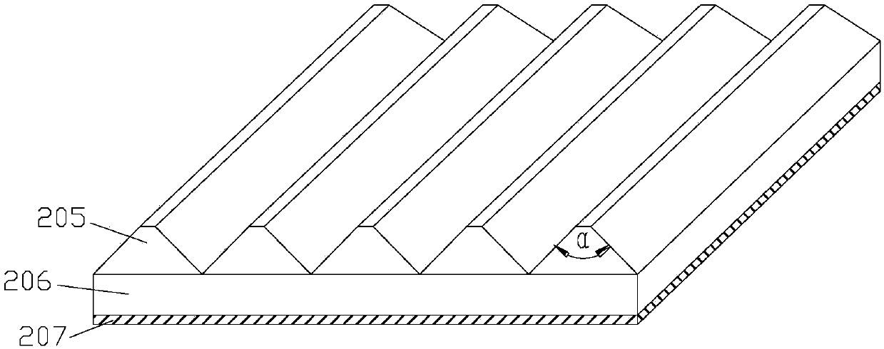
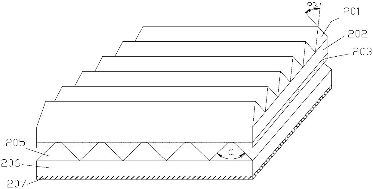
[0030] attached figure 1 with attached figure 2 It is the schematic diagram of embodiment 1.

[0031] The thickness of the base film 206 of the first optical film is 125 μm; the distance between the prism structures 205 is 60 μm, the angle α between the two sides is 90°, and the flat angle platform width at the top is 3 μm; the thickness of the back coating 207 is 5 μm, and the haze is 8%.

[0032] The second optical film is a prism film, the thickness of the base film 202 is 125 μm; the distance between the prism structures 201 is 24 μm, and the angle β between two sides is 90°.

[0033] The included angle between the prism orientation of the first optical film and the prism orientation of the second optical film is 90°.

[0034] The adhesive layer 203 has a thickness of 2 μm. The back of the second optical film prism film is coated with an adhesive layer 203 , then bonded to the first optical film, and cured by ultraviolet light.

Embodiment 2

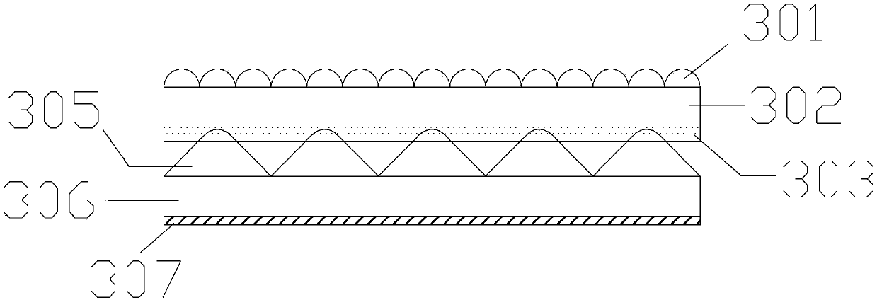
[0036] attached image 3 with attached Figure 4 It is the schematic diagram of embodiment 2.

[0037] The thickness of the base film 306 of the first optical film is 188 μm; the pitch of the prism structure 305 is 50 μm, the angle γ between the two sides is 93°, and the radius of the top fillet is 5 μm; the thickness of the back coating 307 is 4 μm, and the haze is 15%.

[0038] The second optical film is a microlens film, the thickness of the base film 302 is 100 μm, and the radius of the microlens hemisphere 301 is 25 μm.

[0039] The adhesive layer 303 has a thickness of 1 μm. The second optical film microlens film is coated with an adhesive layer 303 on the back, and then bonded to the first optical film and cured by thermal curing.

Embodiment 3

[0041] attached Figure 5 with attached Figure 6 It is the schematic diagram of embodiment 3.

[0042] The first optical film base film 406 has a thickness of 250 μm. The pitch of the prism structure 405 is 70 μm, the angle δ between the two sides is 88°, the width of the flat-angle platform is 5 μm, and the depth of the rough structure of the platform is 1 μm; the thickness of the back coating 407 is 6 μm, and the haze is 20%.

[0043] The second optical film is a diffusion film, the thickness of the base film 402 is 75 μm, the thickness of the diffusion layer 401 is 18 μm, and the haze is 80%.

[0044] The thickness of the adhesive layer 403 is 3 μm. Coat the adhesive layer 403 on the back of the diffusion film of the second optical film, then attach it to the first optical film, and cure it by ultraviolet light.


PUM


Abstract

The invention discloses a multi-layer optical film. The film comprises a first layer optical membrane and a second layer optical membrane. The first layer optical membrane is a prism membrane. The second layer optical membrane is one kind of a prism membrane, a diffusion membrane and a micro-lens membrane. The second layer optical membrane is coated with an adhesive layer. The first layer opticalmembrane and the second layer optical membrane are adhered together through the adhesive layer. According to the invention, due to the design of the prism structure, the adhesion strength between themultiple optical membranes can be improved by 50% or more than that of the current optical composite membrane; through the improving of the adhesion strength, the multiple optical membranes are free from problems of difficult layering and difficult stripping in following cutting, assembling and use; the cutting yield is improved; and the module assembly yield is improved.

Description

technical field [0001] The invention belongs to the technical field of liquid crystal modules, and in particular relates to a multilayer optical film for a liquid crystal module. Background technique [0002] Liquid crystal display technology is the mainstream technology of flat panel display, and liquid crystal display is widely used in mobile phones, tablet computers, monitors, televisions and other display devices. In order to ensure the picture quality of the liquid crystal module, multiple optical films must be used in the backlight module, such as prism film, diffusion film, microlens film, etc. With the demand for ultra-clear and thin design of liquid crystal modules, new requirements are also put forward for the design of optical diaphragms. At present, it is a common practice to bond such as prism film, diffusion film, and microlens film together through an adhesive to form an optical composite film. Specifically, the sharp corners of the prism are pierced into the...

Claims


Application Information

Patent Timeline
Patent Type & Authority Applications(China)
IPC IPC(8): G02B5/04G02B5/02G02B3/00
CPCG02B3/0006G02B5/021G02B5/045
Inventor 颜奇旭翟才金路健
Owner CHANGZHOU HUAWEI ADVANCED MATERIAL
Why Eureka
Try Eureka