
A large-mode-field bending-resistant single-mode fiber with parabolic cores coupled with lobe-shaped cores

A single-mode fiber, parabolic technology, applied in the direction of multi-layer core/clad fiber, clad fiber, optics, etc., can solve the problem of low yield in mass production of single-mode multi-core fiber with large mode field, air holes in photonic crystal fiber It is difficult to manufacture and the optical power of double-clad fiber is limited, so as to achieve high-power laser output, high-power single-mode laser output, and improve thermal resistance and single-mode characteristics.

Active Publication Date: 2019-10-25
BEIJING JIAOTONG UNIV
View PDF7 Cites 0 Cited by
  • Summary
  • Abstract
  • Description
  • Claims
  • Application Information

AI Technical Summary

Problems solved by technology

[0012] In order to overcome the limitation of the numerical aperture of the existing traditional optical fiber, the limited optical power of the single-core multi-doped rare earth ion region double-clad optical fiber, the difficulty of making the air hole of the photonic crystal fiber, and the low mass production yield of the single-mode multi-core optical fiber with large mode field, Due to the limited diameter of the core layer of the petal-shaped fiber, the bending sensitivity of the multi-groove fiber, and the difficulty in manufacturing the parabolic fiber, a large mode field bending-resistant single-mode fiber with a parabolic core coupled to the petal core is proposed.

Method used


Image

  • A large-mode-field bending-resistant single-mode fiber with parabolic cores coupled with lobe-shaped cores
  • A large-mode-field bending-resistant single-mode fiber with parabolic cores coupled with lobe-shaped cores
  • A large-mode-field bending-resistant single-mode fiber with parabolic cores coupled with lobe-shaped cores

Examples


Embodiment 1

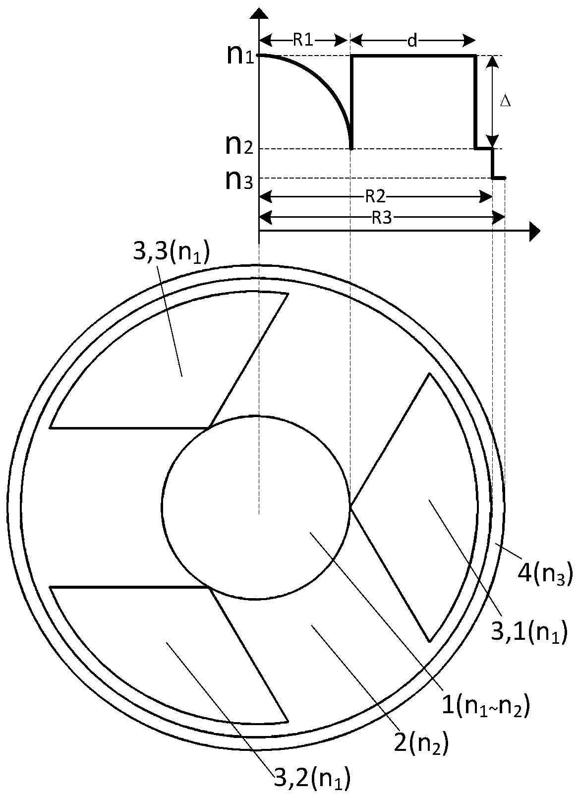
[0026] Large-mode-field bend-resistant single-mode fiber with parabolic core coupled to 3-lobed cores, see figure 1 . The center of the optical fiber is a rare earth ion-doped core area (1), and three lobe-shaped cores (3,1), (3,2), (3, 3), inner cladding (2), outer cladding (4), N=3 in this example;

[0027] The type of rare earth ion doped in the rare earth ion-doped core region (1), the lobe-shaped fiber core (3,1), (3,2), and (3,3) are all erbium ions.

[0028] The center of the rare earth ion-doped core area (1) and the lobe-shaped fiber cores (3,1), (3,2), and (3,3) have the same refractive index;

[0029] The maximum relative refractive index difference Δ=(n1-n2)=0.005 in the core region (1) doped with rare earth ions, the refractive index of the inner cladding (2) is smaller than the refractive index of the lobe-shaped core (3,1), and the outer cladding (4) The refractive index of is less than the refractive index of the inner cladding (2)

[0030] The diameter of ...

Embodiment 2

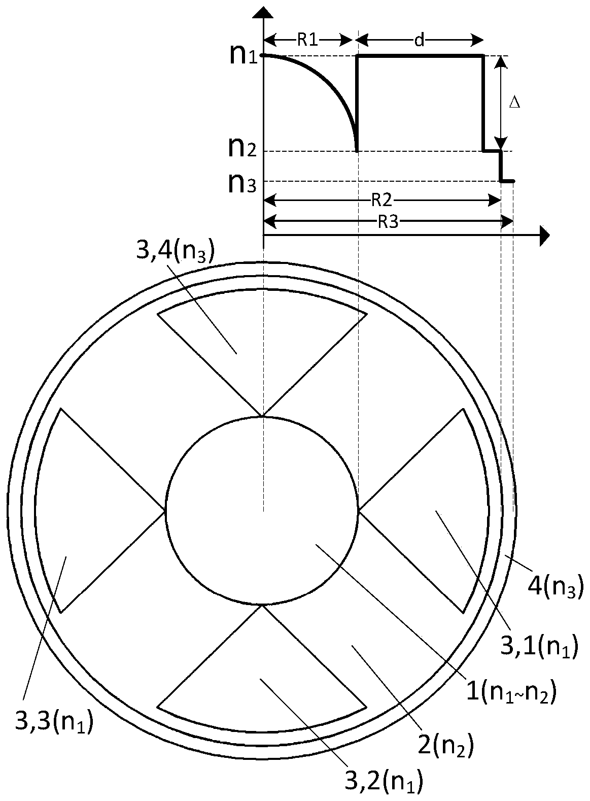
[0032] Large-mode-field bending-resistant single-mode fiber with parabolic core coupling and 4-lobed cores, see figure 2 . The center of the optical fiber is a rare earth ion-doped core area (1), and four lobe-shaped cores (3,1), (3,2), (3, 3), (3,4), inner cladding (2), outer cladding (4), N=4 in this example;

[0033] The type of rare earth ion doped in the rare earth ion-doped core region (1), the lobe-shaped fiber cores (3,1), (3,2), (3,3), and (3,4) are all erbium ions.

[0034] The center of the rare earth ion-doped core region (1) and the lobe-shaped cores (3,1), (3,2), (3,3), and (3,4) have the same refractive index;

[0035] The maximum relative refractive index difference Δ=(n1-n2)=0.004 in the core region (1) doped with rare earth ions, the refractive index of the inner cladding (2) is smaller than the refractive index of the lobe-shaped core (3,1), and the outer cladding (4) The refractive index of is less than the refractive index of the inner cladding (2)

...

Embodiment 3

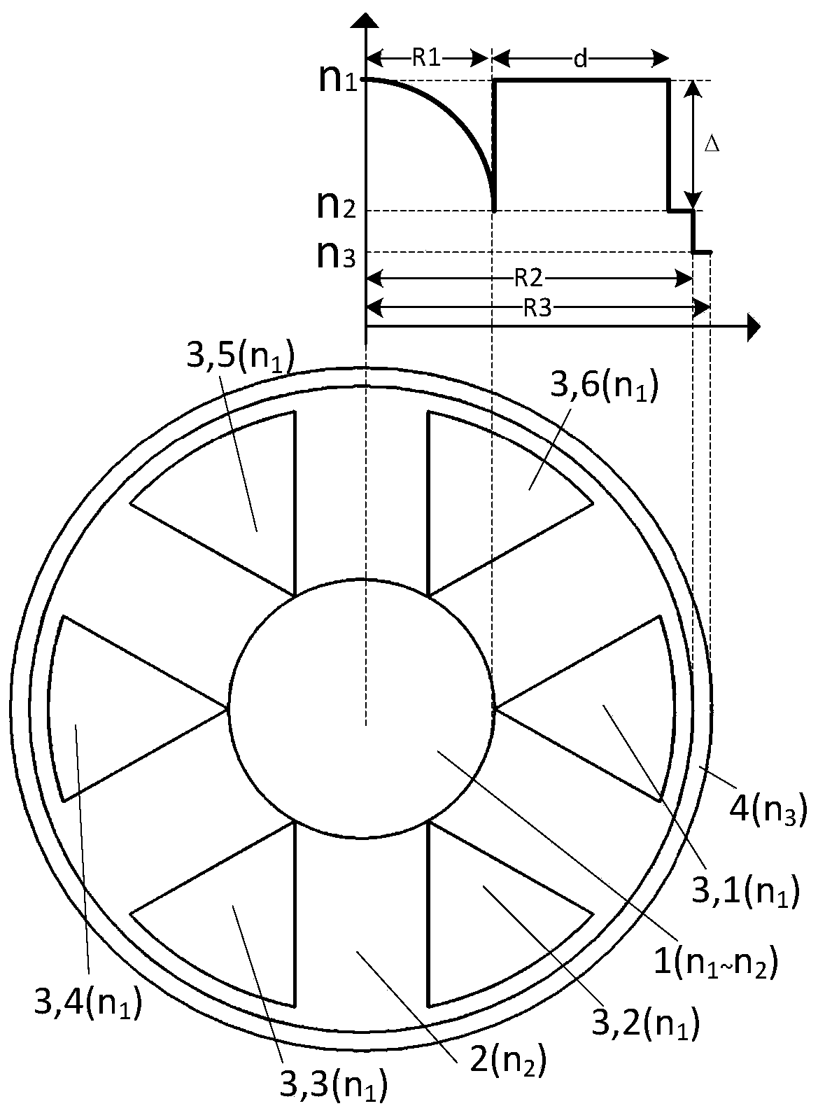
[0038] Large-mode-field bending-resistant single-mode fiber with parabolic core coupling and 6-lobed cores, see image 3 . The center of the optical fiber is a rare earth ion-doped core area (1), and six lobe-shaped cores (3,1), (3,2), (3, 3), (3,4), (3,5), (3,6), inner cladding (2), outer cladding (4), N=6 in this example;

[0039] Doped rare earth ion core region (1), lobe core (3,1), (3,2), (3,3), (3,4), (3,5), (3,6) doping The rare earth ion types are all erbium ions.

[0040] Center of rare earth ion core region (1), lobe cores (3,1), (3,2), (3,3), (3,4), (3,5), (3,6) The refractive index is equal;

[0041] The maximum relative refractive index difference Δ=(n1-n2)=0.004 in the core region (1) doped with rare earth ions, the refractive index of the inner cladding (2) is smaller than the refractive index of the lobe-shaped core (3,1), and the outer cladding (4) The refractive index of is less than the refractive index of the inner cladding (2)

[0042] The diameter o...


PUM


Abstract

The invention discloses a parabolic core coupling segmented-cladding core large mode field bending-resistant single-mode fiber, and belongs to high-power fiber amplifiers, laser devices and special fibers. The center of the fiber is a rare earth ion doped core area (1), an inner clad layer (2), N segmented-cladding fiber cores (3, 1)...(3, N) and an outer clad layer (4) are distributed from insideto outside, the N segmented-cladding fiber cores are uniformly distributed around the rare earth ion doped core area (1) and are the same in radius and radian, the refractivity profile of the rare earth ion doped core area (1) is in a parabolic shape, maximum relative refractive index difference delta is (n1-n2), the refractive indexes n1 of the segmented-cladding fiber cores are equal, and the refractive index n2 of the inner clad layer (2) is lower than that of the segmented-cladding fiber cores. The maximum relative refractive index difference delta is of the parabolic core is larger than0.002, and the single-mode fiber is easily manufactured by a traditional method and solves the problems of poor bending property of a segmented-cladding fiber and high manufacturing difficulty of a parabolic fiber. The segmented-cladding fibers cores can be prepared from fiber preform, materials are saved, manufacture is facilitated, and the single-mode fiber is applicable to large-scale production.

Description

technical field [0001] The invention relates to a large-mode-field bending-resistant single-mode optical fiber with a parabolic core coupled to a lobe-shaped core, and belongs to the fields of high-power optical fiber amplifiers, lasers, and special optical fibers. Background technique [0002] Rare earth-doped fiber amplifiers or lasers use ion fibers doped with rare earth elements (Nd, Sm, Ho, Er, Pr, Tm, Yb, etc.), and use the stimulated emission mechanism to achieve direct amplification of light. [0003] With its excellent performance and low price, fiber lasers have been widely used in optical fiber communication, industrial processing, medical treatment, military and other fields. In 2010, a continuous laser with 10kW power has been reported. With the development of laser technology applications, material processing, space communication, laser radar, photoelectric countermeasures, laser weapons, etc., high-power, high-quality lasers are required, and the single-mode o...

Claims


Application Information

Patent Timeline
Patent Type & Authority Patents(China)
IPC IPC(8): G02B6/02G02B6/036
CPCG02B6/02009G02B6/02333G02B6/03688
Inventor 宁提纲马绍朔李晶王一群王建帅
Owner BEIJING JIAOTONG UNIV
Learn More