
Landfill leachate biochemical treatment system

A technology for landfill leachate and biochemical treatment, which is applied in the direction of polluted groundwater/leachate treatment, biological water/sewage treatment, water/sewage treatment, etc. High cost and other problems, to save investment cost and operating energy consumption, reduce the probability of water flow dead angle, and avoid the effect of water flow short circuit

Pending Publication Date: 2018-04-13
GARDEN ENVIRONMENTAL PROTECTION
View PDF7 Cites 1 Cited by
  • Summary
  • Abstract
  • Description
  • Claims
  • Application Information

AI Technical Summary

Problems solved by technology

[0004] Since the activity of anaerobic bacteria is significantly affected by temperature, the optimum temperature is 30-35°C. Therefore, in order to maintain an efficient anaerobic reaction, the anaerobic reactor needs heat preservation treatment and external heat source, which increases the operation of the anaerobic reaction process. Cost; and in the denitrification-nitrification stage, the wastewater temperature is usually controlled at 30-35°C, but since the heat energy released by nitrifying bacteria during the metabolic process will cause the water temperature to rise, in order to ensure the stability of the biochemical process, an additional cooling tower is required to cool down , resulting in complex system operation and high energy consumption; moreover, there are dead corners of water flow in each nitrification tank and denitrification tank during operation, and the operation efficiency is low; Complexity, low operating efficiency, high energy consumption, and high operating costs

Method used


Image

  • Landfill leachate biochemical treatment system
  • Landfill leachate biochemical treatment system

Examples


Embodiment Construction

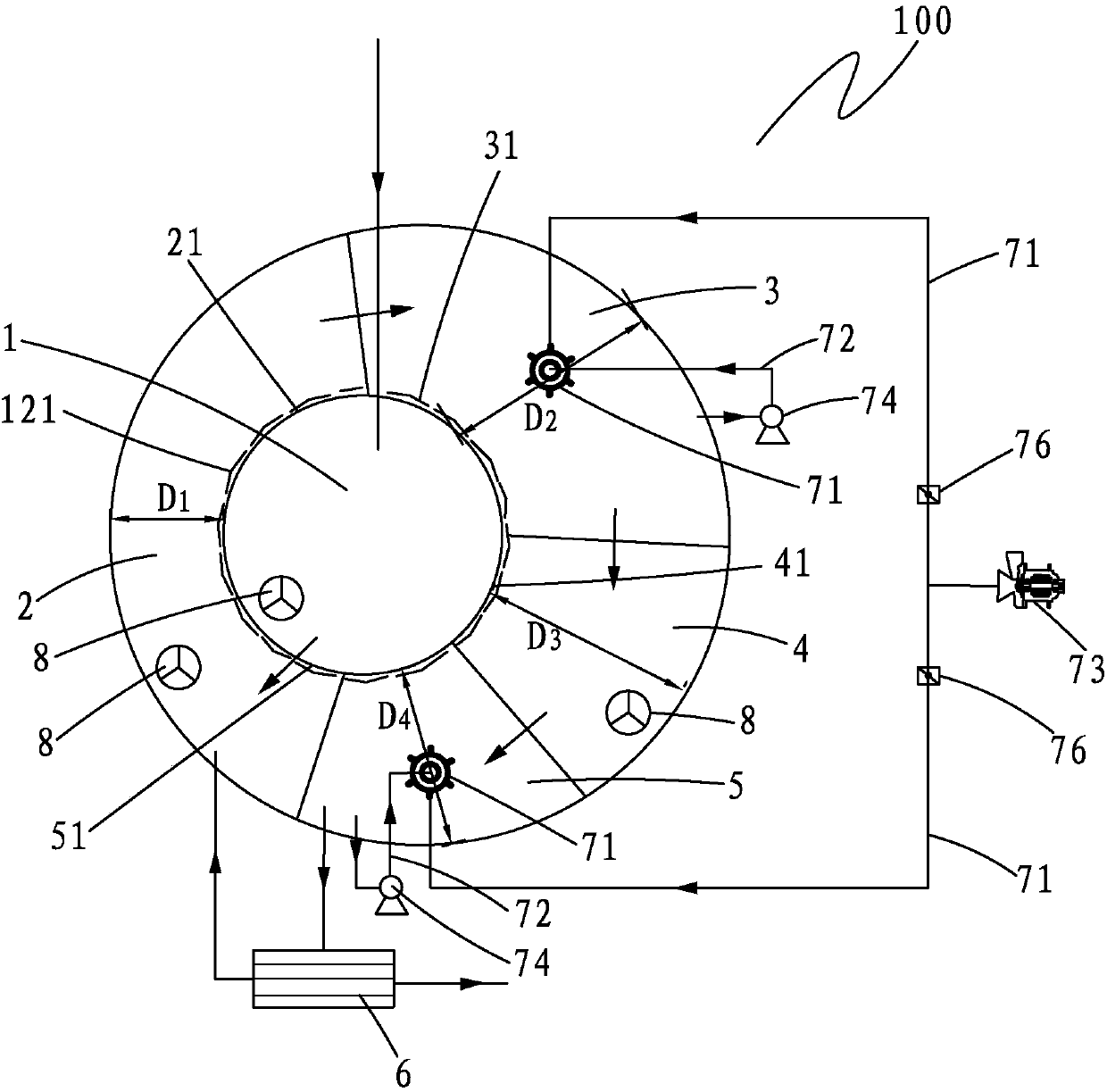
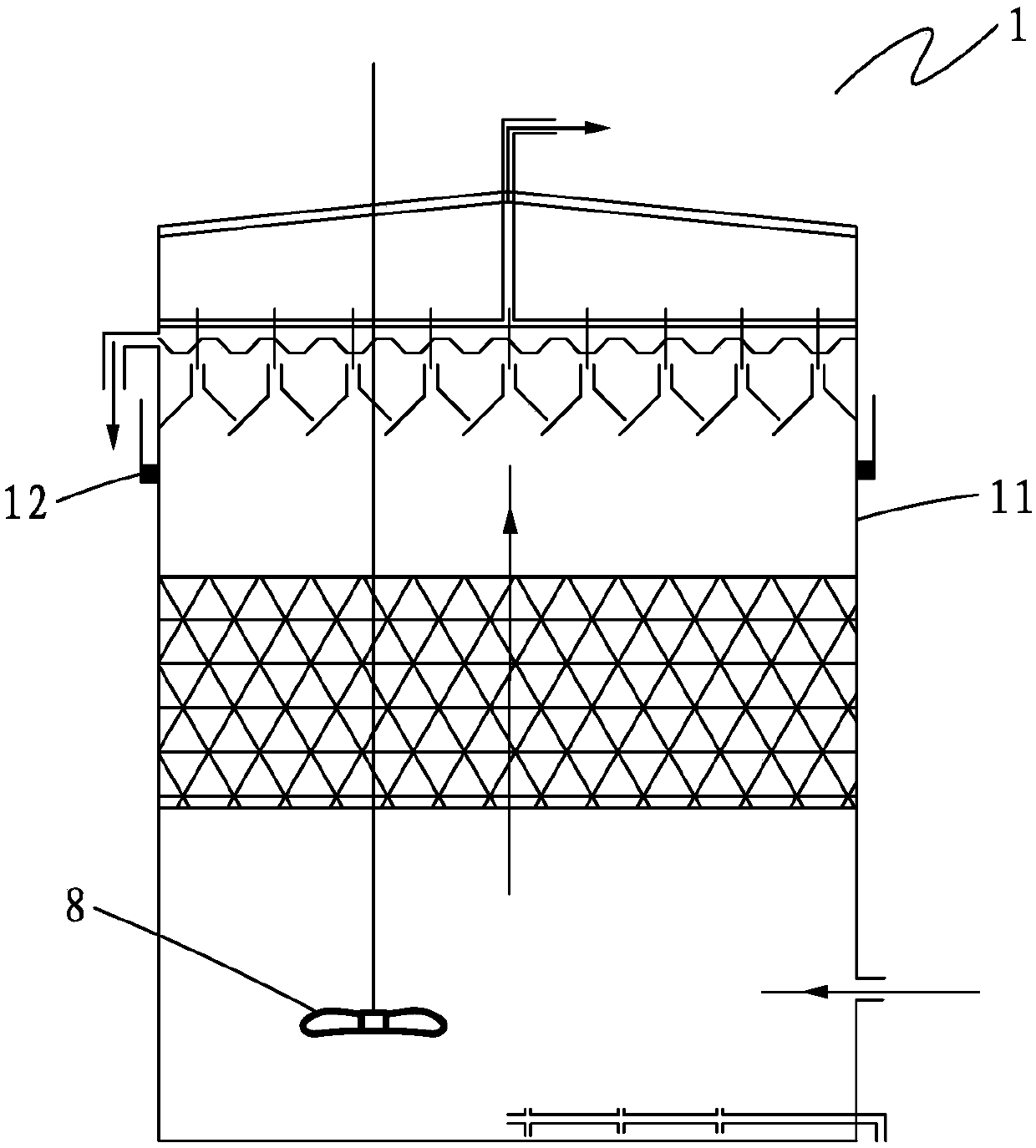
[0020] see figure 1 , a biochemical treatment system 100 for landfill leachate according to the present invention, comprising an anaerobic reactor 1, a first-level denitrification tank 2, a first-level nitrification tank 3, a second-level denitrification tank 4, a second-level nitrification tank 5, and an ultrafiltration device 6. The ultrafiltration device 6 is connected to the secondary nitrification tank 5 and the primary denitrification tank 2 respectively, and the anaerobic reactor 1, the primary denitrification tank 2, the primary nitrification tank 3, and the secondary denitrification tank 4 and the secondary nitrification tank 5 are sequentially connected and connected, and the primary denitrification tank 2, the primary nitrification tank 3, the secondary denitrification tank 4, and the secondary nitrification tank 5 are respectively attached to the anaerobic reactor 1 Set, the first-level denitrification tank 2, the first-level nitrification tank 3, the second-level ...


PUM


Abstract

The invention provides a landfill leachate biochemical treatment system. The system comprises an anaerobic reactor, a first-level denitrification pool, a first-level nitrification pool, a second-leveldenitrification pool, a second-level nitrification pool and an ultrafiltration device, wherein the first-level denitrification pool, the first-level nitrification pool, the second-level denitrification pool and the second-level nitrification pool are each attached to the anaerobic reactor, the first-level denitrification pool, the first-level nitrification pool, the second-level denitrification pool, and the second-level nitrification pool are circularly distributed with the anaerobic reactor as a center, so as to form an eccentric circle structure, the width of the center of the first-leveldenitrification pool is smaller than the center of any other nitrification pool, a tank of the anaerobic reactor is a heat conduction tank, and attachment surfaces between the denitrification pools aswell as the nitrification pools and the anaerobic reactor are all heat conduction surface layers. The landfill leachate biochemical treatment system lowers the probability of water flow dead ends, ensures that leachate is mixed fully, prevents water short circuit, has a better treatment effect of organic matters and total nitrogen, and reduces investment costs and running energy consumption.

Description

【Technical field】 [0001] The invention belongs to the field of landfill leachate treatment, in particular to a biochemical treatment system for landfill leachate. 【Background technique】 [0002] Incineration plant landfill leachate is a kind of organic wastewater with high COD and ammonia nitrogen concentration, complex properties, and difficult to treat. The COD concentration usually reaches 40000-80000mg / L, and the ammonia nitrogen concentration is above 1000mg / L. At present, the biochemical treatment method of landfill leachate in incineration plants is mainly "anaerobic + denitrification - nitrification + MBR process". The anaerobic treatment stage of this process has the advantages of high organic matter treatment efficiency, less residual sludge, and recyclable biogas. ; At the same time, the denitrification-nitrification treatment stage can maintain high sludge concentration through MBR technology, and the sludge concentration usually reaches 15-30g / L, which has a goo...

Claims


Application Information

Patent Timeline
Patent Type & Authority Applications(China)
IPC IPC(8): C02F9/14C02F103/06
CPCC02F1/444C02F3/286C02F2103/06
Inventor 卓瑞锋李泽清林春明陈新芳刘信源
Owner GARDEN ENVIRONMENTAL PROTECTION
Learn More