Nitrogen and carbon removal integrated equipment

A technology for denitrification and equipment, applied in chemical instruments and methods, dehydration/drying/thickened sludge treatment, water/sludge/sewage treatment, etc. Incomplete denitrification and other problems, to achieve the effect of realizing sludge resource utilization and stable utilization, improving sedimentation performance, and ensuring a low-oxygen environment

Inactive Publication Date: 2018-04-20
湖南千幻科技有限公司
View PDF0 Cites 0 Cited by
  • Summary
  • Abstract
  • Description
  • Claims
  • Application Information

AI Technical Summary

Problems solved by technology

[0003] Due to the unsound sewage collection facilities in our country, the rainwater and the sewage discharged from industrial production merge into the drainage system, resulting in the low C / N ratio of the influent water quality of the sewage discharged from industrial production in my country. When the minimum value is reached, incomplete denitrification reaction will occur, which will affect the efficiency of nitrogen and phosphorus removal
Moreover, due to excessive aeration, surfactant action or denitrification reaction, micro-bubbles are generated, which reduces the density of the sludge, causing the sludge to float and generate foam, which affects the sedimentation and biochemical performance of the sludge. Therefore, it is necessary to use physical, Chemical and other methods reduce the formation of foam, but there are problems such as secondary pollution, unstable operation, and high operating costs
On the other hand, there are a large number of toxic and refractory pollutants in the sewage, which are wrapped on the surface of activated sludge flocs for a long time and cannot be degraded or detached, resulting in mass transfer obstruction, resulting in nitrifying or denitrifying bacteria not being able to obtain nutrient supply in time and causing bacterial biochemical performance. become worse
In addition to the problems of hindered sludge mass transfer and low nitrogen removal efficiency, problems such as large surplus sludge production and difficulty in resource treatment are also major problems faced by existing sewage treatment

Method used


Image

  • Nitrogen and carbon removal integrated equipment

Examples


Embodiment Construction

[0015] In order to make the object, technical solution and advantages of the present invention clearer, the present invention will be further described in detail below in conjunction with the accompanying drawings and embodiments. It should be understood that the specific embodiments described here are only used to explain the present invention, not to limit the present invention.

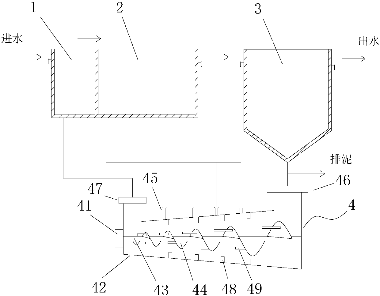
[0016] see figure 1 , figure 1 It is a structural schematic diagram of the present invention.

[0017] An integrated equipment for nitrogen and carbon removal includes anoxic tank 1, aerobic tank 2, sedimentation tank 3, and sludge separator 4; the anoxic tank 1, aerobic tank 2, and sedimentation tank 3 are connected in sequence; the The anoxic tank 1 is provided with a water inlet, and the settling tank 3 is provided with a water outlet and a sludge discharge port; the sludge separator 4 includes a sludge separator main body 42, a stirring motor 41, a stirring shaft 43, and a spiral blade 44; B...


PUM


Abstract

The invention discloses nitrogen and carbon removal integrated equipment. The equipment comprises an anoxic tank, an aerobic tank, a settling tank and a sludge separator, wherein the sludge separatorcomprises a sludge separator body, a stirring motor, a stirring shaft and a helical blade; the helical blade is arranged on the stirring shaft; and the screw pitch of the helical blade is gradually reduced from a sludge inlet side to a sludge outlet side. During the process of advancing of sludge in the sludge separator body, with the gradual reducing of the screw pitch of the helical blade, greatinternal pressure is produced inside the sludge separator body, the volume of the sludge is continuously reduced, and as gas density is far lower than the sludge floc density, gas is discharged intothe aerobic tank from an overflow opening, a degassing process is realized, anoxic environment of the anoxic tank is guaranteed, the settling performance of the sludge is improved, expansion and floating of the sludge and the generation of bubbles are controlled, and the effluent quality is optimized.

Description

technical field [0001] The invention relates to the technical field of sewage treatment, in particular to an integrated equipment for nitrogen and carbon removal. Background technique [0002] With the acceleration of urban development and industrialization, sewage treatment has become a hot environmental issue that people focus on. Sewage discharged from industrial production such as pharmaceuticals, landfill leachate, chemical fertilizers, chemicals, aquaculture, and food has the characteristics of high COD and high ammonia nitrogen, and it is difficult to treat, especially the problem of difficult discharge of ammonia nitrogen. The treatment of ammonia-nitrogen-containing organic wastewater mainly adopts the anoxic / aerobic biochemical process (A / O process), and uses the principle of nitrification / denitrification for simultaneous decarbonization (COD) and denitrification. [0003] Due to the unsound sewage collection facilities in our country, the rainwater and the sewage...

Claims


Application Information

Patent Timeline
Patent Type & Authority Applications(China)
IPC IPC(8): C02F3/30C02F11/12C02F101/16
CPCC02F3/302C02F11/121C02F2101/16
Inventor 不公告发明人
Owner 湖南千幻科技有限公司
Why Eureka
Try Eureka