
Denitration system for removing nitrogen oxide in sintering flue gas and flue gas denitration method

A technology for sintering flue gas and nitrogen oxides, which is applied in the fields of flue gas treatment and environmental engineering, can solve the problems of high investment and operating costs, high operating temperature CO, waste of resources, etc., to save transportation and storage costs, reduce Investment costs and operating costs, the effect of saving transportation costs

Pending Publication Date: 2018-05-04
李幸辉
View PDF3 Cites 1 Cited by
  • Summary
  • Abstract
  • Description
  • Claims
  • Application Information

AI Technical Summary

Problems solved by technology

Some outstanding problems in some sintering flue gas treatment processes include: 1) A single desulfurization process cannot meet the entire requirements of flue gas emissions; 2) The combined desulfurization and denitrification process lacks the treatment of dioxin and heavy metal pollutants; 3) After the desulfurization process Adding denitrification process, dioxin emission reduction process or heavy metal pollutant treatment process alone will cause problems such as high investment and operating costs; 4) There are problems of easy blockage, corrosion, and high cost in the operation of equipment to varying degrees; 5) There is no comparison Good harmless treatment and comprehensive utilization of by-products, resulting in waste of resources
However, due to the high activation temperature of CO reduction and the unstable concentration of CO in flue gas, this will inevitably cause fluctuations in denitrification efficiency, which is difficult to adapt to the future 100㎎ / Nm 3 (in NO 2 Calculated, sintering reference oxygen 16%) emission standard

Method used


Image

  • Denitration system for removing nitrogen oxide in sintering flue gas and flue gas denitration method
  • Denitration system for removing nitrogen oxide in sintering flue gas and flue gas denitration method
  • Denitration system for removing nitrogen oxide in sintering flue gas and flue gas denitration method

Examples


Embodiment 1

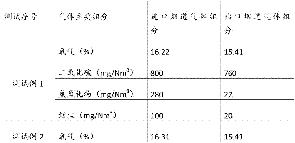
[0051] Raw gas composition: oxygen 16.2%, nitrogen 68.39%, water 10.2%, carbon dioxide 5.2%, sulfur dioxide 800㎎ / Nm 3 , nitrogen oxides 280㎎ / Nm 3 , soot content 100㎎ / Nm 3 .

[0052] Denitration agent composition: hydrogen 60.15%, oxygen 0.07%, carbon monoxide 6.45%, methane 21.24%, carbon dioxide 1.82%, CnHm 2.44%, nitrogen 7.83%, calorific value 3916Kcal / Nm 3

[0053] The flue gas temperature at the inlet of the denitrification system is 150°C, and the gas flow rate is 60,000m 3 / h. After the detection and analysis of the online detection equipment installed at the outlet of the denitrification tower, the main components of the outlet gas are as follows: Oxygen: 16.36% Sulfur dioxide: 760㎎ / Nm 3 Nitrogen oxides: 22㎎ / Nm 3 Soot content: 20㎎ / Nm 3 .

Embodiment 2-4

[0055] The process flow and steps are the same as in Example 1. The flue gas flow rate and main flue gas components of each embodiment remain unchanged, and the temperature and pressure conditions controlled by the system remain unchanged. The reaction results are shown in Table 1.


PUM


Abstract

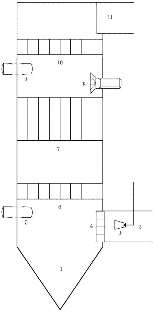
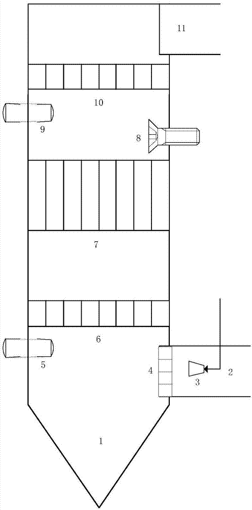
The invention provides a denitration system for removing nitrogen oxide in sintering flue gas. The denitration system comprises a tower body, an inlet flue and an outlet flue, wherein the tower body comprises an ash deposition bucket, a first catalyst layer ash cleaning device, a first catalyst layer, a second catalyst layer, a second catalyst layer ash blowing device, a third catalyst layer ash cleaning device and a third catalyst layer, which are arranged in sequence from bottom to top. The denitration system provided by the invention has the prominent characteristics that coke oven gas or natural gas is used as a denitration agent; the gas denitration agent is introduced so that the transportation and storage cost of the denitration agent is saved and secondary pollution is avoided; meanwhile, waste gas also can be effectively utilized and very good technical effects of saving cost and protecting environment are realized.

Description

technical field [0001] The invention relates to the technical field of environmental engineering, in particular to the technical field of flue gas treatment, in particular to a system and a flue gas removal method for removing nitrogen oxides in sintering flue gas. Background technique [0002] Sintering flue gas mainly comes from the sintering of iron ore in iron and steel enterprises, and the main pollutants in the emissions include particulate matter, sulfur dioxide, nitrogen oxides, and dioxins. Some outstanding problems in some sintering flue gas treatment processes include: 1) A single desulfurization process cannot meet the entire requirements of flue gas emissions; 2) The combined desulfurization and denitrification process lacks the treatment of dioxin and heavy metal pollutants; 3) After the desulfurization process Adding denitrification process, dioxin emission reduction process or heavy metal pollutant treatment process alone will cause problems such as high inve...

Claims


Application Information

Patent Timeline
IPC IPC(8): B01D53/90B01D53/88B01D53/56
CPCB01D53/86B01D53/8631B01D53/869B01D53/88B01D53/90B01D2251/202B01D2251/204B01D2251/208B01D2258/0283
Inventor 李幸辉贾纤张东辉王峰安晓波高峰毕艳国史先培许淑娜吴轩余则俊薛红赵海成
Owner 李幸辉
Learn More