A kind of preparation method of catalytic cracking anti-calcium catalyst
A catalytic cracking and catalyst technology, applied in physical/chemical process catalysts, chemical instruments and methods, hydrocarbon oil cracking, etc., can solve the problem of low removal rate and achieve the effect of increasing total liquid yield and gasoline liquid yield
- Summary
- Abstract
- Description
- Claims
- Application Information
AI Technical Summary
Problems solved by technology
Method used
Image

Examples
Embodiment 1
[0035] (1) 12.82 kilograms of kaolin is beaten, add 0.99 kilograms of zirconium chloride, 0.91 kilograms of titanium chloride, filter,
[0036] (2) Dry and roast the filter cake obtained in step (1) at a temperature of 500° C. for 1 hour,
[0037] (3) re-beating and grinding the calcined material in (2), so that the average particle size is ≤5 μm,
[0038] (4) Add 11.65 kilograms of aluminum sol, 3.5 kilograms of modified REY successively in (3), acidify into gel,
[0039] (5) spray drying, the received particulate matter is roasted, washed and filtered, and rinsed with 0.45 kg of ammonium dihydrogen phosphate,
[0040] (6) Prepare the catalyst, which is denoted as catalyst KG-1.
Embodiment 2
[0042] (1) 18.46 kilograms of halloysite are beaten, add 1.78 kilograms of zirconium chloride, 1.53 kilograms of titanium chloride, filter,
[0043] (2) Dry and roast the filter cake obtained in step (1) at a temperature of 550° C. for 1.5 hours,
[0044] (3) re-beating and grinding the calcined material in (2), so that the average particle size is ≤5 μm,
[0045] (4) Add 12.59 kilograms of aluminum sol, 4.2 kilograms of modified REY successively in (3), acidify into gel,
[0046] (5) spray drying, the received particulate matter is roasted, washed and filtered, and rinsed with 0.50 kg of ammonium monohydrogen phosphate,
[0047] (6) Prepare the catalyst, which is denoted as catalyst KG-2.
Embodiment 3
[0049] (1) With 17.95 kilograms of kaolin beating, add 2.08 kilograms of zirconium chloride, 1.49 kilograms of titanium chloride, filter,
[0050] (2) Dry and roast the filter cake obtained in step (1) at a temperature of 600°C for 2 hours,
[0051] (3) re-beating and grinding the calcined material in (2), so that the average particle size is ≤5 μm,
[0052] (4) add 4.49 kilograms of pseudo-boehmite and 4.9 kilograms of modified REY successively in (3), acidify into gel,
[0053] (5) spray drying, the received particulate matter is roasted, washed and filtered, and rinsed with 0.62 kilograms of ammonium dihydrogen phosphate,
[0054] (6) Prepare the catalyst, which is denoted as catalyst KG-3.
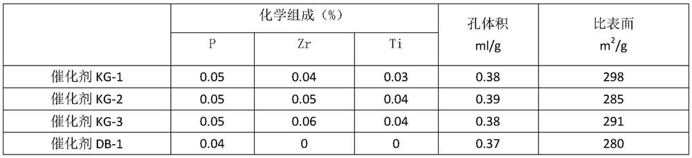
[0055] Analysis Catalyst KG-1, Catalyst KG-2, Catalyst KG-3, and Catalyst DB-1 are common catalysts without anti-calcium modification produced by Huicheng Environmental Protection Technology. The analysis result of catalyst in the example is as follows
[0056] Table 1 catalyst ana...
PUM
 Abstract
Description
Claims
Application Information
 - R&D
- Intellectual Property
- Life Sciences
- Materials
- Tech Scout
- Unparalleled Data Quality
- Higher Quality Content
- 60% Fewer Hallucinations
Browse by: Latest US Patents, China's latest patents, Technical Efficacy Thesaurus, Application Domain, Technology Topic, Popular Technical Reports.
© 2025 PatSnap. All rights reserved.Legal|Privacy policy|Modern Slavery Act Transparency Statement|Sitemap|About US| Contact US: help@patsnap.com