

Directional diagram reconfigurable antenna and phased array thereof
A technology for reconstructing antennas and patterns, applied to antenna arrays, individually powered antenna arrays, antennas, etc., and can solve the problem of large frequency offset of the reconfigurable unit of the array antenna, low radiation gain of the array antenna unit, and phased array. The problem of high antenna array profile, to achieve the effect of easy processing and integration, high gain, and improved radiation gain
- Summary
- Abstract
- Description
- Claims
- Application Information
AI Technical Summary
Problems solved by technology
Method used
Image

Examples
Embodiment 1
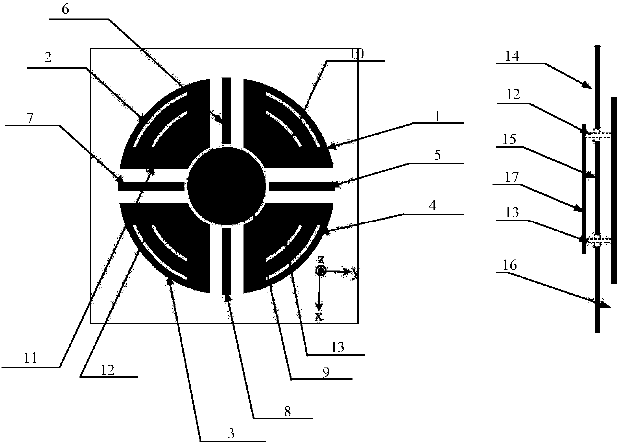
[0040] The dielectric substrate used in this embodiment is a polytetrafluoroethylene (F4BM) material with a relative permittivity of 4.4; the radius of the fan-shaped radiation patch is approximately equal to 0.7 waveguide wavelengths, and the angle of the fan-shaped radiation patch is 90°. The area of the radiating patch is approximately 0.324 waveguide wavelengths squared.
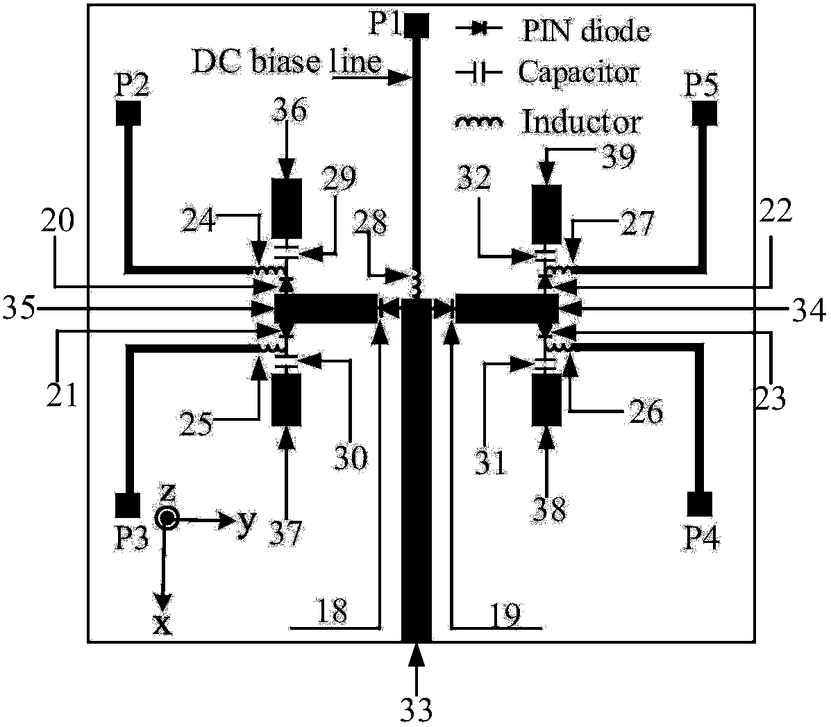
[0041] The feed ports of the four working modes of the antenna described in this embodiment are shown in the following table:
[0042]
[0043] Mode LD: Coaxial probe 12 feeds power, switches 18 and 21 are turned on, switches 19, 20, 22 and 23 are turned off, the radiation pattern is biased to the direction of phi=164°, and the angle theta=30° to the normal direction of the offset unit , the maximum radiation gain is 7.2dBi, the 3dB beam coverage range is in the phi=164° plane, theta is from -10.2° to 60.0°, the center frequency is 5.3GHz, and the -10dB bandwidth range is 5.147-5.417GHz;
[0044] M...
Embodiment 2
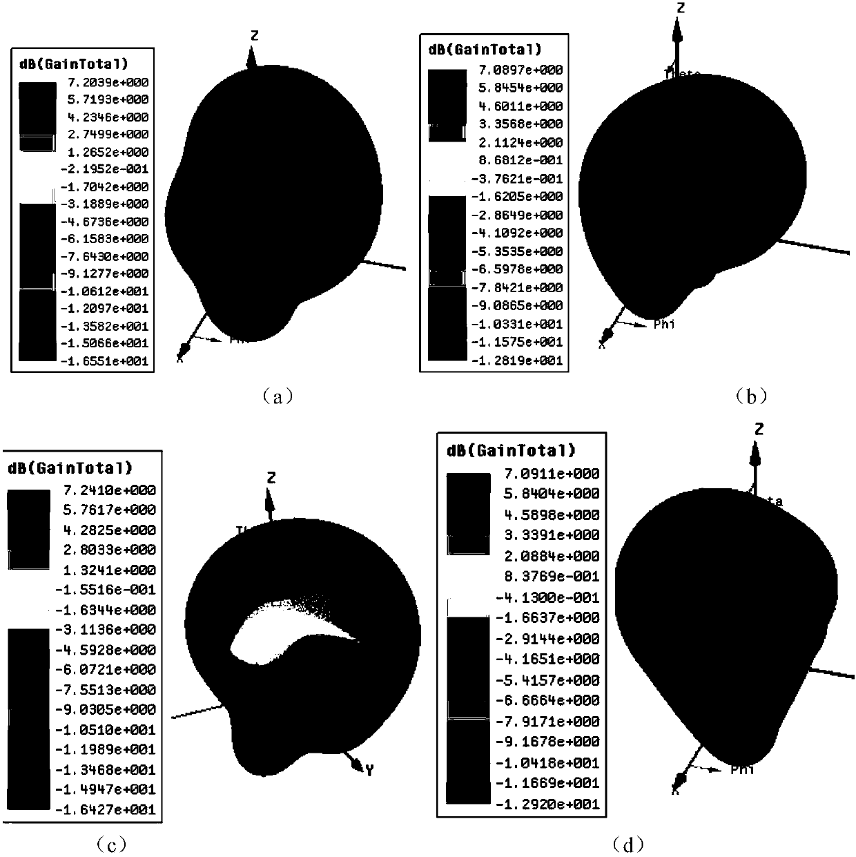
[0049] This embodiment provides a linear phased array with a reconfigurable pattern, and its structural schematic diagram is as follows Figure 5 As shown, in order to bias the radiation pattern of the reconfigurable antenna unit toward the XOZ plane or the YOZ plane, the antenna described in Embodiment 1 is rotated 32° counterclockwise, and this antenna is used as a unit antenna; the feeding structure of this embodiment adopts The coaxial feed replaces the above feed network. In order to achieve a good match, the feed probe needs to deviate from the edge point of the fan-shaped patch for a certain distance. The structure of the antenna unit is as follows: Figure 6 As shown, the three-dimensional radiation pattern of its S parameter and resonance frequency point is shown as Figure 7 shown. It can be seen from the figure that the radiation patterns of the four modes LU, LD, RU, and RD of the antenna unit deviate from the normal direction by 30°, and have good matching perfor...
Embodiment 3
[0054] This embodiment provides a planar two-dimensional phased array with a reconfigurable pattern, and its structural diagram is as follows Figure 9 As shown, the antenna unit adopts the antenna unit described in Embodiment 2, and also adopts coaxial feeding; the unit antennas are arranged into a 5×5 two-dimensional array, and the interval between the unit antennas is about 0.71 wavelengths. The edge spacing between the antennas is about 0.035 wavelengths; the dielectric substrate used in this embodiment is a polytetrafluoroethylene (F4BM) material with a relative permittivity of 4.4; by controlling the working mode of the reconfigurable unit in the array, it can be realized Two-dimensional large-angle scanning of the XOZ and YOZ planes.
[0055] When the units of the planar two-dimensional array are in the RD mode, it can realize angular scanning in the negative half plane of YOZ, and the S parameters corresponding to the angular scanning range and the maximum scanning ang...
PUM
 Abstract
Description
Claims
Application Information