
Power plant desulfurization wastewater treatment system
A desulfurization wastewater and treatment system technology, applied in the direction of gaseous effluent wastewater treatment, water/sewage treatment, heating water/sewage treatment, etc., can solve the problems of large water ratio, limited amount of hot slag, and affecting the value of bottom slag, etc., to achieve Add value, avoid high costs, and achieve zero-emission effects
- Summary
- Abstract
- Description
- Claims
- Application Information
AI Technical Summary
Problems solved by technology
Method used
Image

Examples
Embodiment Construction
[0020] In order to make the technical problems, technical solutions and advantages to be solved by the present invention clearer, the following will describe in detail with reference to the drawings and specific embodiments.
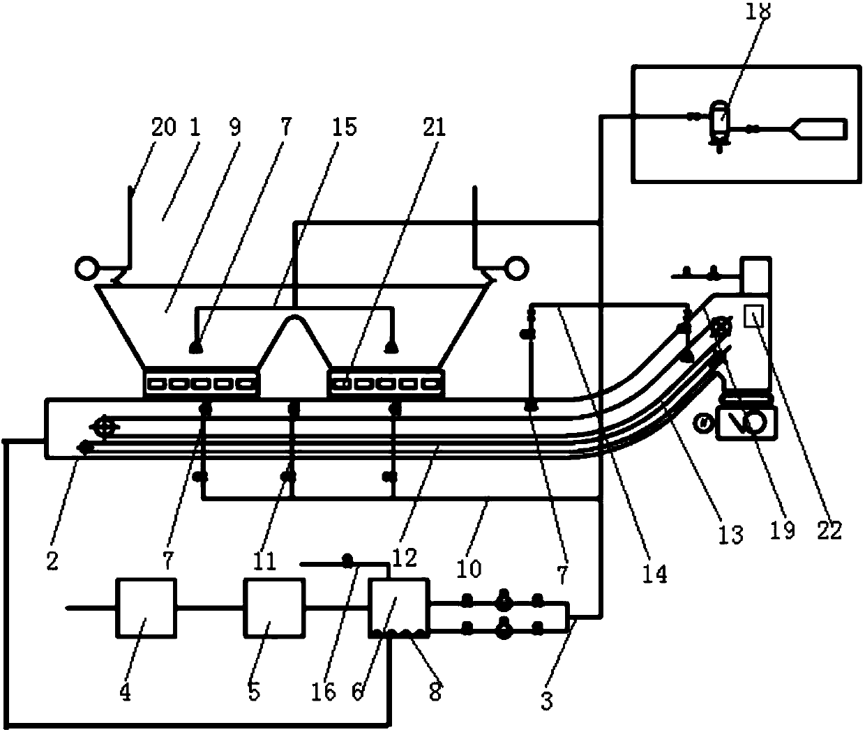
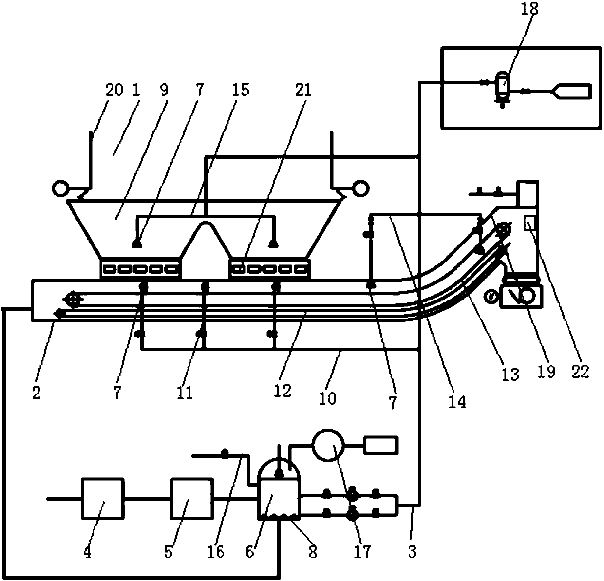
[0021] The invention provides a power plant desulfurization wastewater treatment system, such as Figure 1-2 As shown, it includes a slag drying machine 2 and a spray pipe 3, the slag drying machine 2 is arranged below the boiler 1, more specifically, it is arranged below the slag well 9, and the water inlet end of the spray pipe 3 is connected with a concentrating device and The water storage device 6, the concentration device includes a tubular microfiltration membrane 4 and a vibrating membrane 5, a number of nozzles 7 are arranged on the spray pipe 3, and the nozzles 7 are located above the dregs drying machine 2, the water storage device 6 is provided with a heating device 8, and the dregs is dried The head 19 is provided with a temperature sensor a...
PUM
 Abstract
Description
Claims
Application Information