An image acquisition device and acquisition method for microparticle imaging velocimetry system

An image acquisition device and particle imaging velocimetry technology, which is applied in measurement devices, fluid velocity measurement, velocity/acceleration/impact measurement, etc., can solve the problem of not meeting the requirements of Micro-PIV image lighting, high requirements for epi-illumination light source light intensity, Problems such as the inability to obtain flow field images through the camera, achieve the effects of coaxial adjustment, high pulse energy, and convenient adjustment

Active Publication Date: 2019-08-20
SOUTHEAST UNIV
View PDF4 Cites 0 Cited by
  • Summary
  • Abstract
  • Description
  • Claims
  • Application Information

AI Technical Summary

Problems solved by technology

[0003] Micro-PIV first needs to use a fluorescence microscope to collect high-brightness images of fluorescent tracer particles in micro-scale channels. However, the size of fluorescent tracer particles is generally on the scale of hundreds of nanometers to several microns, and the frame rate of the camera is dozens of per second. The frame is even higher, so the exposure time is very short, and the light intensity requirements for the epi-illumination light source are high. The existing fluorescence microscope is equipped with a halogen lamp or a mercury lamp epi-illumination light source, which can only meet the illumination needs of general fluorescent biological samples, but Unable to meet the requirements of illumination light intensity for Micro-PIV image acquisition, it is necessary to use a high-power laser as the epi-emission excitation light source
[0004] The fluorescence microscope of the Micro-PIV system adopts an infinity-corrected optical path system. If the laser beam is expanded and directly directed into the microscope, the distance from the incident light entrance of the microscope to the objective lens is more than 50 cm, and the aperture is only about 3 cm. The narrow and long light path will make the laser Almost parallel to the objective lens, the objective lens converges on the focal point of the microscope objective lens, so it can only illuminate a very small area in the center of the flow field on the focal plane, which cannot meet the illumination requirements of the Micro-PIV image acquisition flow field range, and cannot Obtain the flow field image observed by the microscope through the camera

Method used


Image

  • An image acquisition device and acquisition method for microparticle imaging velocimetry system
  • An image acquisition device and acquisition method for microparticle imaging velocimetry system
  • An image acquisition device and acquisition method for microparticle imaging velocimetry system

Examples


Embodiment Construction

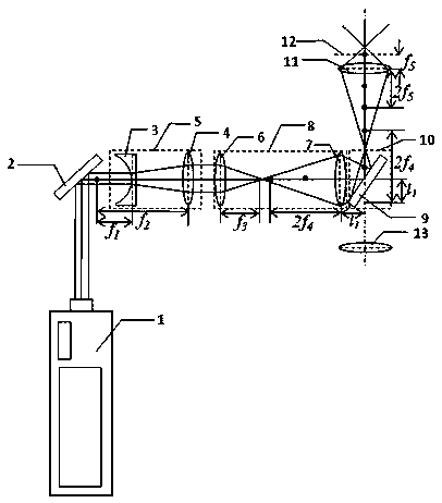
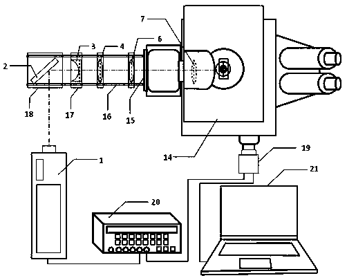
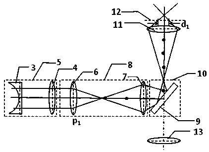
[0031] Such as figure 1 , figure 2 As shown, the laser light emitted by the double-pulse laser 1 is attenuated by the beam splitter 2 and reflected into the beam expander module 5. After beam expansion, the laser beam is converged at one point by the convex lens 6, and the convergent point is passed through the convex lens 7 installed in front of the fluorescent module 10. The dichroic mirror 9 is reflected and imaged at the rear of the microscope objective 11 to form a beam of divergent illumination light entering the microscope objective 11, and finally converges at the front of the focal plane 12 of the microscope objective 11 through the microscope objective 11 to achieve the purpose of increasing the focal plane illumination area. In addition, adjusting the position of the convex lens 6 can change the front and rear positions of the converging point falling behind the microscope objective lens, and correspondingly change the converging point falling in front of the micro...


PUM


Abstract

The invention discloses an image acquisition device and an image acquisition method for a microscopic particle imaging and speed measurement system. The image acquisition device comprises a double-pulse laser device, a beam splitter, a beam expanding module, a fluorescent microscope, an illumination area adjusting module, a CCD camera and a synchronous controller. The controller is connected withthe CCD camera and the double-pulse laser and is used for controlling and realizing the synchronization of the double-pulse laser device and the CCD camera. The pulse laser is attenuated by the beam splitter and is reflected into the beam expanding module. The expanded pulse laser is converged in front of the focal plane of the objective lens of the microscope by the illumination area adjusting module. Through adjusting the illumination area adjusting module, the size of the illumination area can be adjusted. Compared with the prior art, a high-power pulse laser device is adopted as a light source, so that the light intensity of the illumination light is greatly improved. Meanwhile, the size of the illumination area can be adjusted. The requirement of the microscopic particle imaging and speed measurement system on vertical illumination can be met. The signal-to-noise ratio of an acquired image can be improved.

Description

technical field [0001] The invention belongs to the technical field of microscale multiphase flow measurement, and in particular relates to an image acquisition device used in a microscopic particle imaging velocimetry system. Background technique [0002] In recent years, microfluidic chips have been rapidly applied in the fields of biomedicine, chemical engineering, and electronic integrated circuits, such as microfluidic diagnostic chips, chemical synthesis chips, and heat dissipation chips. The function of the microfluidic chip is closely related to the flow characteristics inside the chip. The measurement of the velocity field has become an important topic in the study of micro-scale flow. Effective non-contact experimental method. [0003] Micro-PIV first needs to use a fluorescence microscope to collect high-brightness images of fluorescent tracer particles in micro-scale channels. However, the size of fluorescent tracer particles is generally on the scale of hundred...

Claims


Application Information

Patent Timeline
Patent Type & Authority Patents(China)
IPC IPC(8): G01P5/20G01N21/64
Inventor 许传龙宋祥磊曹丽霞
Owner SOUTHEAST UNIV
Why Eureka
Try Eureka