Anti-impact flux-cored composite solder cake with spiral framework and preparation method thereof
A composite brazing material and impact-resistant technology, which is applied in the manufacture of tools, welding equipment, metal processing equipment, etc., can solve the problems of difficult to accurately control the amount of brazing flux, complicated brazing process, and excessive addition of brazing flux, etc., to achieve easy batch production The effects of chemical production, increased specific surface area, and reduced amount of flux
- Summary
- Abstract
- Description
- Claims
- Application Information
AI Technical Summary
Problems solved by technology
Method used
Image

Examples
specific Embodiment approach
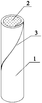
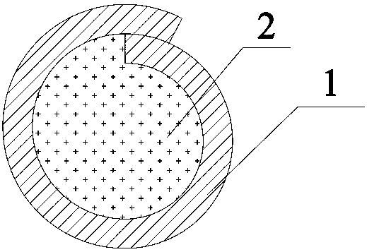
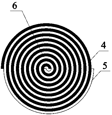
[0032] An impact-resistant flux-cored solder cake with a helical skeleton, the solder cake 6 is composed of narrow-band flux-cored solder 4 and narrow-band material 5 intertwined to form a plane double helix, and the narrow-band flux-cored solder 4 and narrow-band The gap between materials 5 ≤ 0.1 mm; if figure 1 and figure 2 As shown, the narrow-band flux-cored solder 4 includes a solder outer layer 1 and a flux core 2 filled in the solder outer layer 1, and the solder outer layer 1 includes 44 parts by weight. ~46 parts of Ag, 24~26 parts of Zn and 28~30 parts of Cu, and the strip-shaped solder made of Ag, Cu and Zn prepared according to the above ratio is rotated and rolled to have a spiral lap joint 3 The tubular structure, the flux core 2 includes a silver flux core, and the narrow band material 5 is a copper-nickel alloy.
[0033] Further, when the outer brazing material layer 1 is rolled, 0.01-0.025 parts of rare earth is added to Ag, Cu and Zn strip-shaped brazing...
Embodiment 1
[0048] An impact-resistant flux-cored composite solder cake with a spiral skeleton, the thickness of the solder-cored solder cake 6 is 0.1 mm, and the solder-cored solder cake 6 is composed of narrow-band flux-cored solder 4 and narrow-band material 5 intertwined to form a plane double helix shape, the gap between the narrow-band flux-cored solder 4 and the narrow-band material 5 is less than or equal to 0.1 mm; Drug core 2, the brazing material outer layer 1 includes 44 parts of Ag, 24 parts of Zn, and 28 parts of Cu in parts by weight, and is made of Ag, Cu, Zn and rare earth prepared according to the above ratio The ribbon-shaped brazing material is rotated and rolled into a tubular structure with a spiral lap joint 3, such as Figure 4 As shown, the cross-sections of the narrow-band flux core solder 4 and the narrow-band material 5 are both trapezoidal, the flux core 2 includes a silver flux core, and the narrow-band material 5 is a copper-nickel alloy.
[0049] Further, ...
Embodiment 2
[0057] An impact-resistant flux-cored composite solder cake with a spiral skeleton, the thickness of the solder-cored solder cake 6 is 2 mm, and the solder-cored solder cake 6 is composed of narrow-band flux-cored solder 4 and narrow-band material 5 intertwined to form a plane double helix shape, the gap between the narrow-band flux-cored solder 4 and the narrow-band material 5 is less than or equal to 0.1 mm; Drug core 2, the solder outer layer 1 includes 45 parts of Ag, 25 parts of Zn, 29 parts of Cu and 0.02 part of rare earth in parts by weight, and is made of Ag, Cu, Zn, the ribbon-shaped brazing filler material that rare earth is made rotates and rolls and is made into the tubular structure that has helical lap seam 3, as Figure 6 As shown, the cross-section of one end of the narrow-band flux-cored solder 4 and the narrow-band material 5 is a semicircular groove, and the cross-section of the other end is drum-shaped, and the flux flux core 2 includes a silver solder dr...
PUM
| Property | Measurement | Unit |
|---|---|---|
| Thickness | aaaaa | aaaaa |
Abstract
Description
Claims
Application Information
 - Generate Ideas
- Intellectual Property
- Life Sciences
- Materials
- Tech Scout
- Unparalleled Data Quality
- Higher Quality Content
- 60% Fewer Hallucinations
Browse by: Latest US Patents, China's latest patents, Technical Efficacy Thesaurus, Application Domain, Technology Topic, Popular Technical Reports.
© 2025 PatSnap. All rights reserved.Legal|Privacy policy|Modern Slavery Act Transparency Statement|Sitemap|About US| Contact US: help@patsnap.com