Integrated whole autotrophic nitrogen removal device

A full-process autotrophic denitrification and ontology technology, which is applied in the field of integrated full-process autotrophic denitrification devices, can solve the problems of denitrification performance and operation stability limitation, limit denitrification performance, and increase operating costs, and achieve rapid start-up and operation. The effect of stable operation, reducing aeration energy consumption, and increasing the amount of contact

Active Publication Date: 2018-05-18
ZHEJIANG OCEAN UNIV
View PDF7 Cites 13 Cited by
  • Summary
  • Abstract
  • Description
  • Claims
  • Application Information

AI Technical Summary

Problems solved by technology

The traditional biological denitrification process has stable performance, but when treating wastewater with high ammonia nitrogen and low C / N, the denitrification performance is often limited due to the lack of carbon sources, and additional organic matter needs to be added, which increases the operating cost and easily causes the risk of secondary pollution. Conducive to safe and economical operation of the system
In recent years, with breakthroughs in denitrification theory and practice, some new biological denitrification processes are gradually taking shape and a large number of researches and applications have begun. The new denitrification process technology that combines the advantages of short-range nitrification and anammox process is fully autotrophic The denitrification process is a very important one, but due to the influence of sludge sedimentation performance, the whole autotrophic denitrification process operated by activated sludge method needs a long start-up time and the denitrification performance and operation stability are limited

Method used


Image

  • Integrated whole autotrophic nitrogen removal device
  • Integrated whole autotrophic nitrogen removal device
  • Integrated whole autotrophic nitrogen removal device

Examples


Embodiment 1

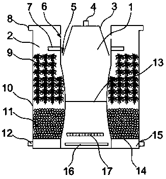
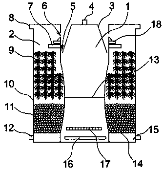
[0024] Such as figure 1 , 2 As shown, an integrated full-process autotrophic denitrification device includes a body 10. A granular sludge chamber 1 and an anaerobic sludge-biofilm chamber 2 are arranged inside the body 10. The granular sludge chamber 1 is sequentially arranged from bottom to top. Inlet water distributor 16, aeration pipe 17 and partition plate 13, anaerobic sludge-biofilm chamber 2 are respectively provided with hanging packing layer 9, accumulation packing layer 11 and water outlet chamber 15 from top to bottom, anaerobic sewage The mud-biofilm chamber 2 is arranged around the outside of the granular sludge chamber 1. The granular sludge chamber 1 is divided into upper and lower parts by a partition plate 13. The upper part is provided with a gas collection hood 3, and the end face of the gas collection hood 3 is provided with a first gas outlet. 4. The upper part of the inner wall of the granular sludge chamber 1 is provided with an annular overflow port 6 ...

Embodiment 2

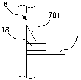
[0031] Such as image 3 , 4 As shown, the further optimization scheme of this embodiment on the basis of Embodiment 1 is: the inner wall of the anaerobic sludge-biofilm chamber 2 is obliquely surrounded and connected with a deflector 701, and the deflector 701 is flush with the bottom surface of the overflow port 6, The deflector 701 is located above the buffer 18, and the buffer 18 is located above the water distributor 7. Using the deflector 701, the wastewater enters the anaerobic sludge-biofilm chamber 2 and fully contacts with the outside air to reduce the oxygen concentration in the wastewater. , to prevent concentrated wastewater from flowing down from the inner wall of the anaerobic sludge-biofilm chamber 2, resulting in uneven distribution of wastewater in the anaerobic sludge-biofilm chamber 2, affecting the effect of denitrification and the corrosive effect on the inner wall, and then using water distribution The device 7 evenly distributes the waste water and flow...

Embodiment 3

[0034] Such as Figure 5 As shown, the further optimization scheme of this embodiment on the basis of embodiment 1 is:

[0035]The surface of the partition plate 13 is preferably evenly distributed with gas-liquid flow holes 13a with a diameter of 3 cm. The ratio of the total area of ​​the round holes to the total area of ​​the partition plate 13 is preferably 0.75:1, and the gas-liquid flow holes 13a on the surface of the partition plate 1 The gas input by the aeration pipe 17 at the bottom is further dispersed evenly to avoid excessive concentration of air bubbles, which is not easy to reproduce and grow aerobic ammonia oxidizing bacteria on the surface of the granular sludge. The surface of the partition plate 13 is evenly distributed with gas-liquid flow holes 13a, and a cross bar 13b is arranged at the bottom of the gas-liquid flow hole 13a, and the lower part of the cross bar 13b is connected with a diverter ball 13c through a connecting rod, and the surface of the diver...


PUM


Abstract

The invention provides an integrated whole autotrophic nitrogen removal device and belongs to the technical field of biological nitrogen removal of wastewater. The device comprises a reaction device body, wherein a granular sludge chamber and an anaerobic sludge-biomembrane chamber are arranged in the body, a water feeding and distributing device, an aeration pipe and a partition board are sequentially arranged in the granular sludge chamber from bottom to top, a filler suspending layer, a filler stacking layer and a water outlet chamber are formed in the anaerobic sludge-biomembrane chamber from top to bottom, the anaerobic sludge-biomembrane chamber surrounds the outer side of the granular sludge chamber, the partition board is arranged in the middle of the granular sludge chamber, a gas-collecting hood is arranged at the upper part, a first gas outlet is formed in the gas-collecting hood, an annular overflow port communicated with the anaerobic sludge-biomembrane chamber is formed in the upper part of the inner wall of the granular sludge chamber, a buffer and a water distributor are connected to the upper part of the inner wall of the anaerobic sludge-biomembrane chamber, and asecond gas outlet is formed in the top. The device can be started in a short time, can effectively intercept sludge to create aerobic and anaerobic environments and improve the system biomass and diversity, occupies little floor space and is good in water treatment effect.

Description

technical field [0001] The invention belongs to the technical field of wastewater biological denitrification, and in particular relates to an integrated whole-process autotrophic denitrification device. Background technique [0002] Nitrogen pollution can easily lead to eutrophication of water bodies, which poses a serious threat to the natural environment and human health. In order to improve the quality of the water environment and ensure the health of people and the healthy development of the ecosystem, biological denitrification has increasingly attracted widespread attention from domestic and foreign societies. The traditional biological nitrogen removal technology is mainly based on the nitrification and denitrification process. In the nitrification stage, ammonia nitrogen is converted into nitrite by ammonia oxidizing bacteria (AOB), and then converted into nitrate by nitrite oxidizing bacteria (NOB); and in the subsequent denitrification process. In the nitrificatio...

Claims


Application Information

Patent Timeline
Patent Type & Authority Applications(China)
IPC IPC(8): C02F3/30C02F101/16
CPCC02F3/301C02F3/302C02F2101/16
Inventor 阳广凤冯丽娟唐思敏穆军刘俊稚杨桥张晓玲高锋
Owner ZHEJIANG OCEAN UNIV
Why Eureka
Try Eureka