
Enhanced nitrogen and phosphorus removal device and method for low-carbon sewage

A technology for nitrogen and phosphorus removal and sewage, which is applied in the direction of chemical instruments and methods, biological treatment devices, biological water/sewage treatment, etc. TN, TP load and other issues, to achieve the effect of strengthening biological nitrogen and phosphorus removal capacity, improving carbon source utilization efficiency, and improving utilization efficiency

Active Publication Date: 2018-05-18
广州市蕴泰电力成套设备有限公司
View PDF5 Cites 5 Cited by
  • Summary
  • Abstract
  • Description
  • Claims
  • Application Information

AI Technical Summary

Problems solved by technology

Although method 1 can increase part of the carbon source, the increased carbon source is suspended COD, which has poor biochemical properties and is not a high-quality carbon source for the nitrogen and phosphorus removal process; method 2 has the same carbon source properties as method 1, and strengthens denitrification for the secondary biochemical system Phosphorus removal efficiency has little effect; Method 3 needs to add anaerobic fermentation tank, which requires 3-4d residence time, which requires a large investment, and the non-polar components in the sediment of the primary sedimentation tank are relatively high, even after anaerobic fermentation treatment, the amount of high-quality carbon source is also Very limited; Method 4 newly added residual sludge digestion supernatant contains high TN and TP in addition to COD, as a carbon source supplement, it will also increase the load of TN and TP in the influent to a certain extent
In fact, the existing methods for improving the utilization efficiency of carbon sources in sewage treatment plants are mainly aimed at the adsorption of organic matter by suspended particles in sewage influent or the digestion of organic matter by residual sludge, without considering the hydrolysis and acidification of colloidal organic matter in sewage to improve its utilization efficiency

Method used


Image

  • Enhanced nitrogen and phosphorus removal device and method for low-carbon sewage
  • Enhanced nitrogen and phosphorus removal device and method for low-carbon sewage
  • Enhanced nitrogen and phosphorus removal device and method for low-carbon sewage

Examples


Embodiment 1

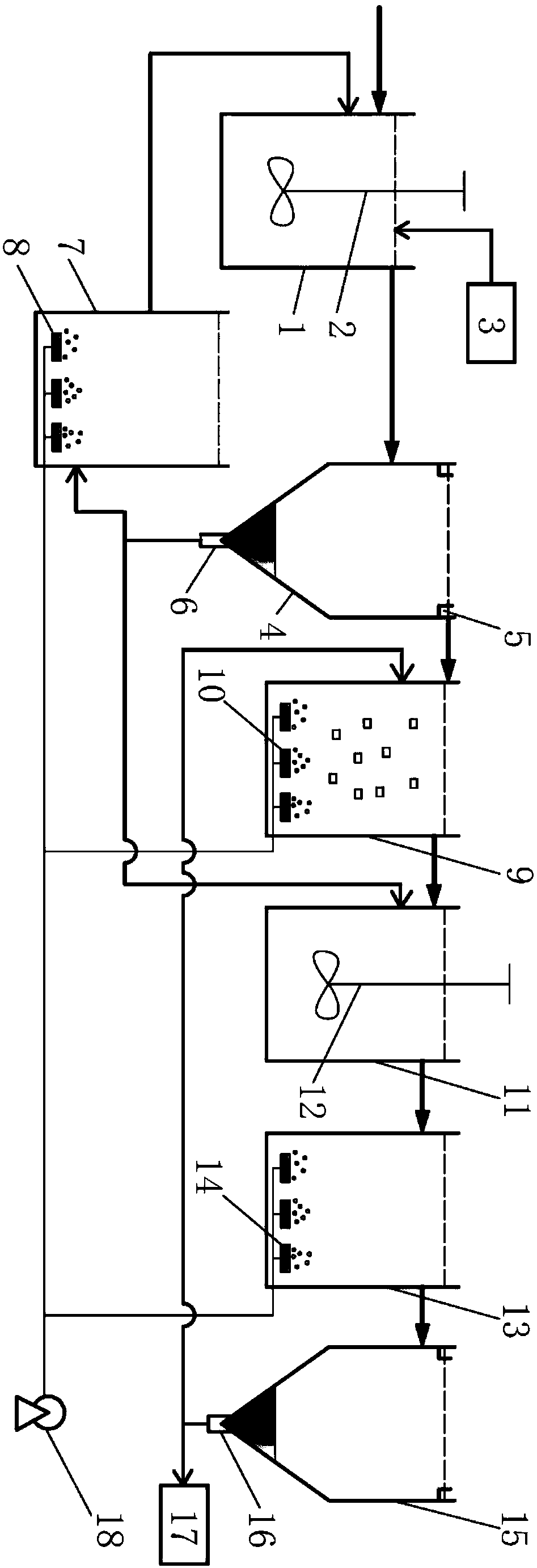
[0075] attached figure 1 is a schematic diagram of the device of the present invention. figure 1 Middle, 1-biosorption tank, 2-biosorption tank mixer, 3-short generation sludge dosing device, 4-sedimentation tank, 5-sedimentation tank outlet weir, 6-sedimentation tank sediment outlet, 7-sludge regeneration Pool, 8-sludge regeneration tank aeration device, 9-nitration reaction tank, 10-nitration reaction tank aeration device, 11-anoxic denitrification tank, 12-anoxic denitrification tank mixer, 13-secondary aeration Pool, 14-secondary aeration tank aeration device, 15-secondary sedimentation tank, 16-secondary sedimentation tank sludge outlet, 17-sludge storage tank, 18-fan.

[0076] Attached below figure 1 The device of the present invention will be further described. An enhanced nitrogen and phosphorus removal device for low-carbon source sewage, comprising a biological adsorption tank (1), a sedimentation tank (4), a nitrification reaction tank (9), an anoxic denitrificat...

Embodiment 2

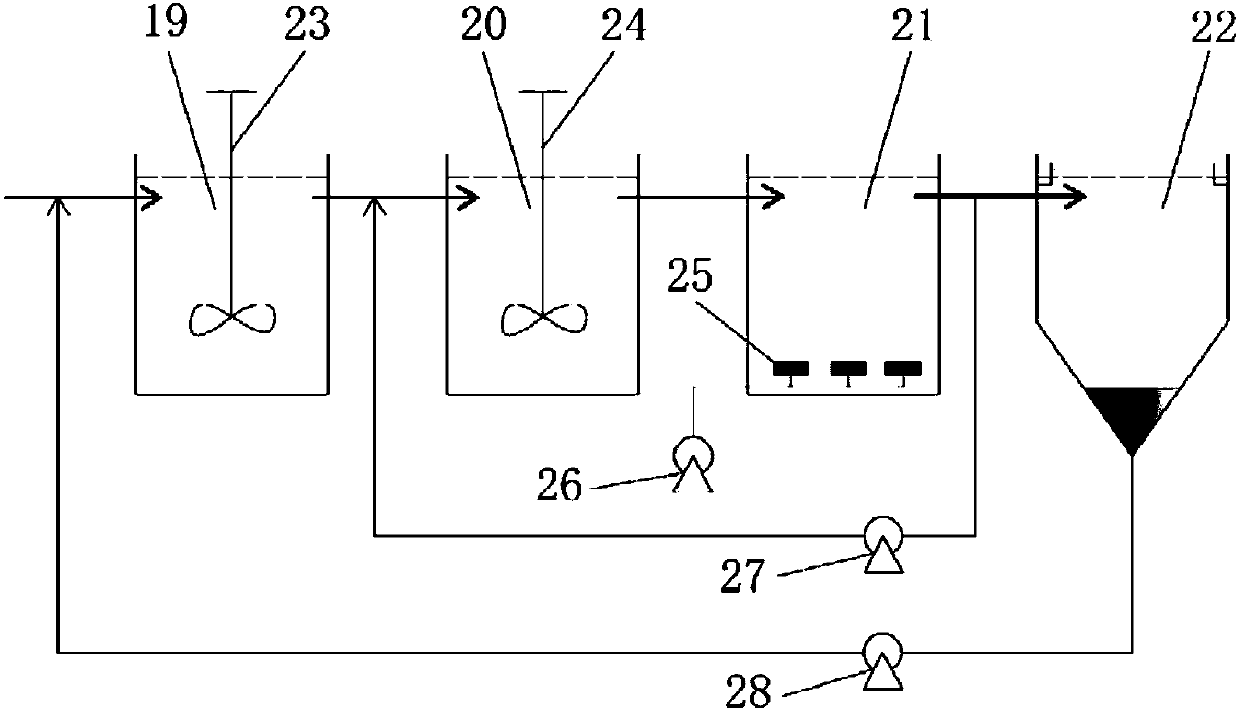
[0088]The influent of my country's sewage treatment plants generally has the problem of low BOD / TN and insufficient carbon sources. For urban sewage with low carbon-to-nitrogen ratio, the present invention adopts adsorption-aerobic (nitrification)-anoxic (denitrification)-aerobic ( AOAO) technical solution. In order to verify the treatment effect of A-O-A-O process on low-carbon source sewage, a set of conventional A 2 The / O processing system is used as a comparison, and the specific process flow is shown in the appendix figure 2 . figure 2 Middle, 19-anaerobic tank, 20-anoxic tank, 21-aerobic tank, 22-sedimentation tank, 23-anaerobic tank mixer, 24-anoxic tank mixer, 25-aeration head, 26-blower, 27 - Sludge return pump, 28 - Nitrification liquid return pump. Regular A 2 The / O treatment system consists of anaerobic tank (19), anoxic tank (20), aerobic tank (21) and sedimentation tank (22). The anaerobic tank (19) has a volume of 20L and a residence time of 1h. One unit ...


PUM

PropertyMeasurementUnit
surface load factoraaaaaaaaaa
dissolved oxygenaaaaaaaaaa

Abstract

The invention discloses an enhanced nitrogen and phosphorus removal device and method for low-carbon sewage. The enhanced nitrogen and phosphorus removal device comprises a biosorption tank, a sedimentation tank, a nitration reaction tank, an anoxic denitrification tank, a secondary aeration tank and a secondary sedimentation tank which are sequentially connected through pipes, and also comprisesa sludge regeneration tank, wherein the biosorption tank is connected with a short-generation sludge feeding device through a pipe; a sediment outlet of the sedimentation tank is connected with the sludge regeneration tank and the anoxic denitrification tank through pipes, and the sludge regeneration tank is connected with the biosorption tank through a pipe; a sludge outlet of the secondary sedimentation tank is connected with the nitration reaction tank through a pipe; an aeration device is arranged on each of the nitration reaction tank, the secondary aeration tank and the sludge regeneration tank. The invention further discloses an enhanced nitrogen and phosphorus removal method for the low-carbon sewage. By using the device for treating the low-carbon sewage, the utilization efficiency of a carbon source can be improved, biological nitrogen and phosphorus removal capability of the device is enhanced, and the operation cost of a sewage treatment plant can be reduced.

Description

technical field [0001] The invention relates to the field of sewage treatment, in particular to an enhanced denitrification and dephosphorization device and method for low-carbon source sewage. Background technique [0002] Nutrient salts such as N and P are important factors for the eutrophication of lakes, rivers, reservoirs and other surface waters. As the country strengthens water pollution control, the control of total nitrogen and total phosphorus in the effluent of sewage treatment plants will become increasingly strict. [0003] In the secondary biochemical treatment process of sewage treatment plants, the removal capacity of TN and TP is closely related to carbon source. It is generally believed that BOD / TN greater than 4 and BOD / TP greater than 20 are the basic conditions for biological nitrogen and phosphorus removal. Insufficient, especially under the condition of lack of high-quality carbon source (BOD), no matter what secondary biochemical treatment process is ...

Claims


Application Information

Patent Timeline
Patent Type & Authority Applications(China)
IPC IPC(8): C02F9/14C02F101/30C02F101/16
CPCC02F9/00C02F2101/105C02F2101/16C02F2101/30C02F3/34C02F3/308C02F1/52C02F2301/046C02F2301/08C02F2203/006C02F2209/08C02F2209/16C02F2209/14Y02W10/10
Inventor 李光辉刘军徐兰李媛张志航潘冠言
Owner 广州市蕴泰电力成套设备有限公司
Learn More