Technology for centralized recycling of coal gas and oil gas in coal chemical engineering industry

A technology of coal chemical industry and gas, which is applied in the direction of chemical instruments and methods, combined devices, and separation of dispersed particles, to achieve the effects of less pollution, safety assurance, and cost saving

Active Publication Date: 2018-06-01
HENAN DRAGON INTO COAL TECH CO LTD +1
View PDF7 Cites 1 Cited by
  • Summary
  • Abstract
  • Description
  • Claims
  • Application Information

AI Technical Summary

Problems solved by technology

Although the cost of membrane separation technology is expensive, but for environmental protection and safety, it has to be used

Method used


Image

  • Technology for centralized recycling of coal gas and oil gas in coal chemical engineering industry
  • Technology for centralized recycling of coal gas and oil gas in coal chemical engineering industry

Examples


Embodiment 1

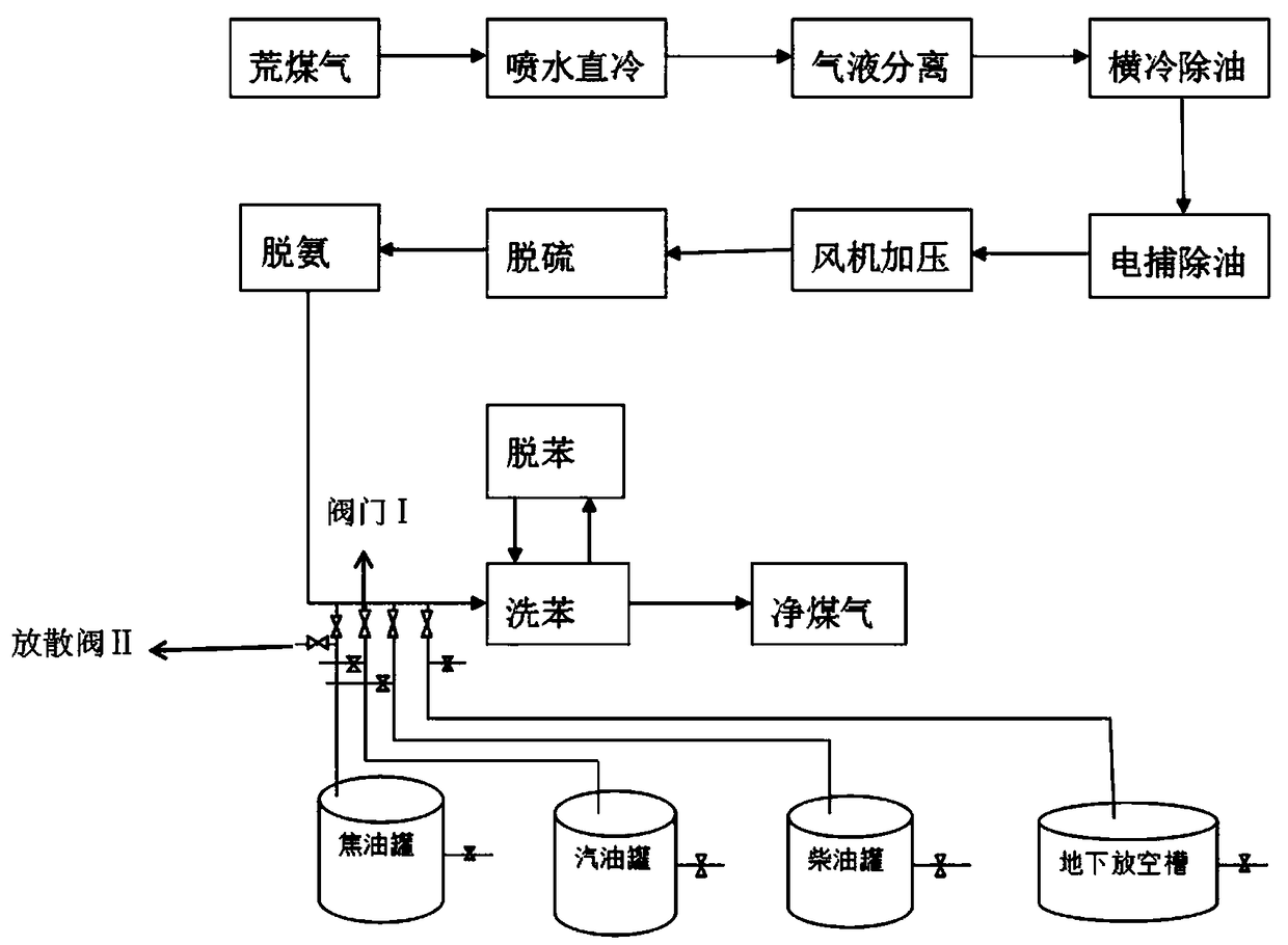
[0028] Such as figure 1 As shown, the coal gas purification process is that the raw coal gas produced by coal pyrolysis is directly cooled by spraying water → gas-liquid separation → horizontal cooling for oil removal → electric capture for oil removal → fan pressurization → desulfurization → deammonization → benzene elution.

[0029] A process for the centralized recovery of coal gas and oil gas in the coal chemical industry. The tar tanks in the coal chemical industry and the co-production of tar to produce gasoline and diesel oil tanks and diesel tanks, and the tank tops of underground emptying tanks are respectively equipped with breathing pipes. The breathing pipeline is connected with the gas positive pressure pipeline before the benzene eluting device after the pressurized fan in the gas purification to form a pipe network together, and the gas pressure in the pipe network is consistent.

[0030] The gas pressure in each tank is consistent with the gas space of the enti...

Embodiment 2

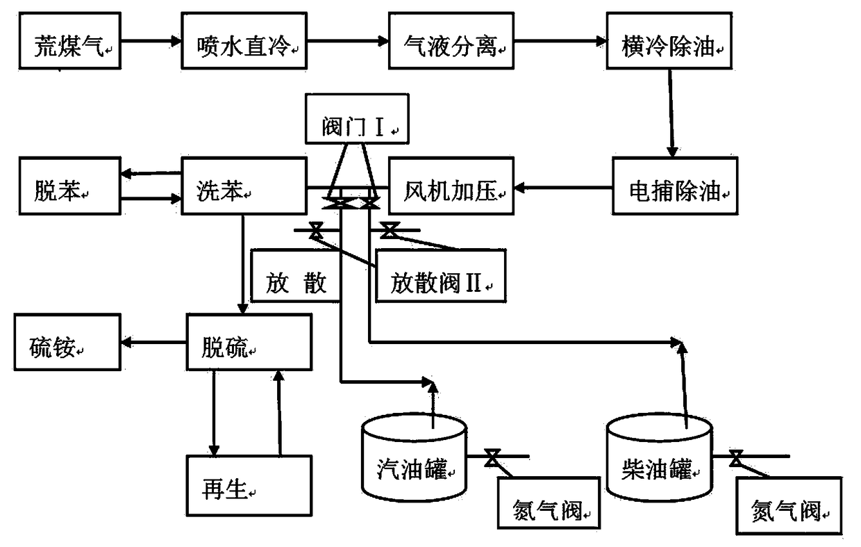
[0034] Such as figure 2 As shown, the purification process of coal gas is that the raw coal gas produced by coal pyrolysis is directly cooled by spraying water → gas-liquid separation → horizontal cooling for oil removal → electric capture for oil removal → fan pressurization → benzene elution → desulfurization → ammonium sulfate, gas get cleansed.

[0035] The tar tanks and tar co-production gasoline and diesel tanks for producing gasoline and diesel oil, and the breathing pipes on the top of the tanks in the underground emptying tanks are still connected to the gas positive pressure pipes in front of the benzene eluting device after the pressurized fan in the gas purification process. Form a pipe network.

[0036] The difference from the gas purification process in Example 1 is that the benzene elution process in Example 2 is placed in front of the desulfurization and ammonium sulfate process. The purpose is to remove the organic matter before the gas desulfurization, so a...


PUM


Abstract

The invention discloses a technology for centralize recycling of coal gas and oil gas in coal chemical engineering industry, and belongs to the field of coal chemical engineering. The technology is characterized in that respiration pipelines that are arranged at the top parts of a tar tank of coal chemical engineering industry, a gasoline tank and a diesel tank are connected with a coal gas pipeline to form a coal gas and oil gas pipeline network which is of a structure that the pressure in each tank is the same with the pressure of gas in the whole pipeline network, the gasoline tank and thediesel tank are used for preparing gasoline and diesel by tar joint production process, and the coal gas pipeline is arranged in front of a benzene elution device for coal gas purifying; the coal gasand oil gas are automatically charged or discharged along with the change of liquid level in each tank, so as to realize the automatic compensation effect of gas pressure; the solvent elution oil in the benzene elution device has stronger compatibility with volatile micromolecular hydrocarbons, benzenes and other organic substances in coal tar, gasoline and diesel, so that the solvent elution oilcan be absorbed, and the collection rate of volatile substances reaches 99%. A device and a method are simple, the implementing is easy, and the better cost and environment protection advantages are realized.

Description

technical field [0001] The invention relates to a process for centralized recovery of coal gas and oil gas in the coal chemical industry, which belongs to the technical field of coal chemical oil gas recovery, and specifically relates to the technical field of coal chemical industry and tar deep processing. Background technique [0002] Crude oil and gasoline and other light oil products stored and sold in oil depots contain a large amount of light hydrocarbon components, which are highly volatile, so it is inevitable that some liquid hydrocarbon components will vaporize and enter the atmosphere in the form of oil and gas , not only waste energy, but also cause environmental pollution and affect human health. [0003] In order to reduce the volatilization of oil and gas, people have designed floating roof tanks, and adopted measures for cooling and heat insulation of the oil tank, but the use of floating roof tanks and breathing valves can only reduce oil and gas evaporation...

Claims


Application Information

Patent Timeline
Patent Type & Authority Applications(China)
IPC IPC(8): B01D53/14B01D50/00B01D53/00
CPCB01D50/00B01D53/00B01D53/002B01D53/1487
Inventor 朱书成王希彬
Owner HENAN DRAGON INTO COAL TECH CO LTD
Why Eureka
Try Eureka