Biomass microwave pyrolysis oriented gasification method and system

A biomass and microwave technology, applied in the direction of chemical instruments and methods, gasification process, physical/chemical process catalysts, etc., can solve the problems of water vapor consumption, increased energy consumption and gas consumption, and low process economy, so as to solve coking Carbon deposition, strong microwave absorption properties, and the effect of eliminating coking carbon deposition

Active Publication Date: 2018-06-05
CHINA PETROLEUM & CHEM CORP +1
View PDF13 Cites 13 Cited by
  • Summary
  • Abstract
  • Description
  • Claims
  • Application Information

AI Technical Summary

Problems solved by technology

However, the catalyst used in this patent uses attapulgite as a carrier, which has the problem of low microwave absorption efficiency, and the oxidation coke suppression treatment cannot solve the structural deactivatio

Method used


Image

  • Biomass microwave pyrolysis oriented gasification method and system

Examples


Embodiment 1

[0065] Mix bio-semi-coke, bio-tar, nickel oxide, potassium hydroxide and water according to the mass ratio of 15:1:2:2:9. Extrusion temperature is 120°C and extrusion speed is 0.15mm / s. The length is 20mm, the extrusion diameter is 2mm, extruded into strips, the size is φ2mm×4mm, and it is dried at 105°C for 4 hours, and roasted at 500°C for 1 hour in a high-temperature flue gas atmosphere.

Embodiment 2

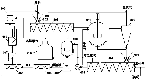
[0067] The biomass microwave pyrolysis directional gasification system of the present invention: as figure 1 As shown, including feed components, microwave pyrolysis components, microwave gasification components and catalyst regeneration components, where:

[0068] The feed assembly includes a feed bin 101 and an unloader I 102 for mixing biomass and catalysts and feeding them to the microwave pyrolysis assembly;

[0069] The microwave pyrolysis component includes a microwave pyrolysis reactor 201, and the microwave pyrolysis reactor 201 is used to receive the raw material from the feed component and pyrolyze it into gaseous volatile components and a small amount of biological semi-coke, gas-solid products Both enter the microwave vaporization assembly.

[0070] The microwave gasification assembly includes a microwave gasification reactor 301 and a gas-solid separator 302. The microwave gasification reactor 201 is provided with a gas outlet connected to the gas-solid separato...

Embodiment 3

[0074] Utilize the catalyst of embodiment 1 and the system of embodiment 2 to carry out the process of biomass pyrolysis directional gasification:

[0075] The biomass raw material and catalyst preheated at 120°C are mixed according to the mass ratio of 1:1, then sent to the feeding bin 101, and then enter the microwave pyrolysis reactor 201 through the unloader 102, and are mixed evenly under the action of its ribbon And heat treatment, when the material system reaches 600 ° C, start to adjust the feed rate 1kg / h and carry out microwave pyrolysis reaction at the same time, the reaction time is 2 minutes, and the microwave power density is 10×10 5 W / m 3 After pyrolysis treatment, the conversion of biomass raw materials consists of pyrolysis volatile component products and a small amount of semi-coke, of which pyrolysis volatile components account for 95%, semi-coke accounts for 5%, and pyrolysis volatile components include about 10%. condensing components. Pyrolysis volatile...


PUM


Abstract

The invention discloses a biomass microwave pyrolysis oriented gasification method and system. The method includes a microwave pyrolysis reaction process, a microwave gasification reaction process anda catalyst recycling regeneration process. An employed catalyst is a catalyst including biological semi-coke, biological tar, nickel oxide and a group I metal hydroxide. The system of the present invention includes a feed assembly, a microwave pyrolysis assembly, a microwave gasification assembly and a catalyst regeneration assembly. The catalyst regeneration assembly includes an oxidation processor, a deashing tank, a dispersion processor, a precipitation processor, an extruder, a baking chamber and a necessary solid-liquid separation device. The method and system of the present invention can catalyze oriented conversion of biomass into syngas to achieve a gas yield of 90% or more, a syngas content of 90% or more, and a H2/CO ratio controlled between 2.0 and 3.0. The system can effectively couple and integrate products and energy during the production process, and achieve a continuous and streamlined process.

Description

technical field [0001] The invention relates to a microwave-assisted biomass pyrolysis directional gasification method and system. Background technique [0002] Biomass energy is rich in resources and is a renewable and environmentally friendly green energy source. Using biomass to produce synthetic gas through pyrolysis and gasification is a promising energy development method. However, the immaturity of biomass pyrolysis gasification technology, low gasification efficiency, the purity of biomass synthesis gas and tar impurities directly restrict the development of biomass synthesis gas bioconversion technology. Therefore, the development of a new type of low-consumption and high-efficiency biomass rapid gasification synthesis gas technology, and the systematic study of key issues such as high tar and low conversion of synthesis gas raw materials from the root cause will solve the bottleneck problem in the promotion of biotechnology and lead the future biomass conversion te...

Claims


Application Information

Patent Timeline
IPC IPC(8): C10J3/66B01J31/28B01J31/40
CPCB01J31/28B01J31/403C10J3/66C10J2300/0916C10J2300/0986C10J2300/123Y02P20/52Y02P20/584
Inventor 王鑫张彪蔡海乐赵丽萍刘继华乔凯宋永一张长安
Owner CHINA PETROLEUM & CHEM CORP
Why Eureka
Try Eureka