
Fin line structure-based terahertz third-harmonic mixer

A sub-harmonic mixer and terahertz technology, applied in the direction of waveguide devices, electrical components, circuits, etc., to achieve the effect of convenient grounding, blocking fundamental wave signals, and less stray signals

Active Publication Date: 2018-06-08
四川众为创通科技有限公司
View PDF5 Cites 11 Cited by
  • Summary
  • Abstract
  • Description
  • Claims
  • Application Information

AI Technical Summary

Problems solved by technology

[0006] The technical problem to be solved by the present invention is to ensure that the DC component in the Schottky diode in the odd mixer is well grounded, and the purpose is to provide a terahertz third harmonic mixer based on a fin wire structure. The line structure ensures that the DC component in the Schottky diode can be well grounded, and solves the common problem of the existing odd-order mixer. The third-order harmonic mixer of the terahertz has fewer stray signals and a high compression point.

Method used


Image

  • Fin line structure-based terahertz third-harmonic mixer
  • Fin line structure-based terahertz third-harmonic mixer
  • Fin line structure-based terahertz third-harmonic mixer

Examples


Embodiment 1

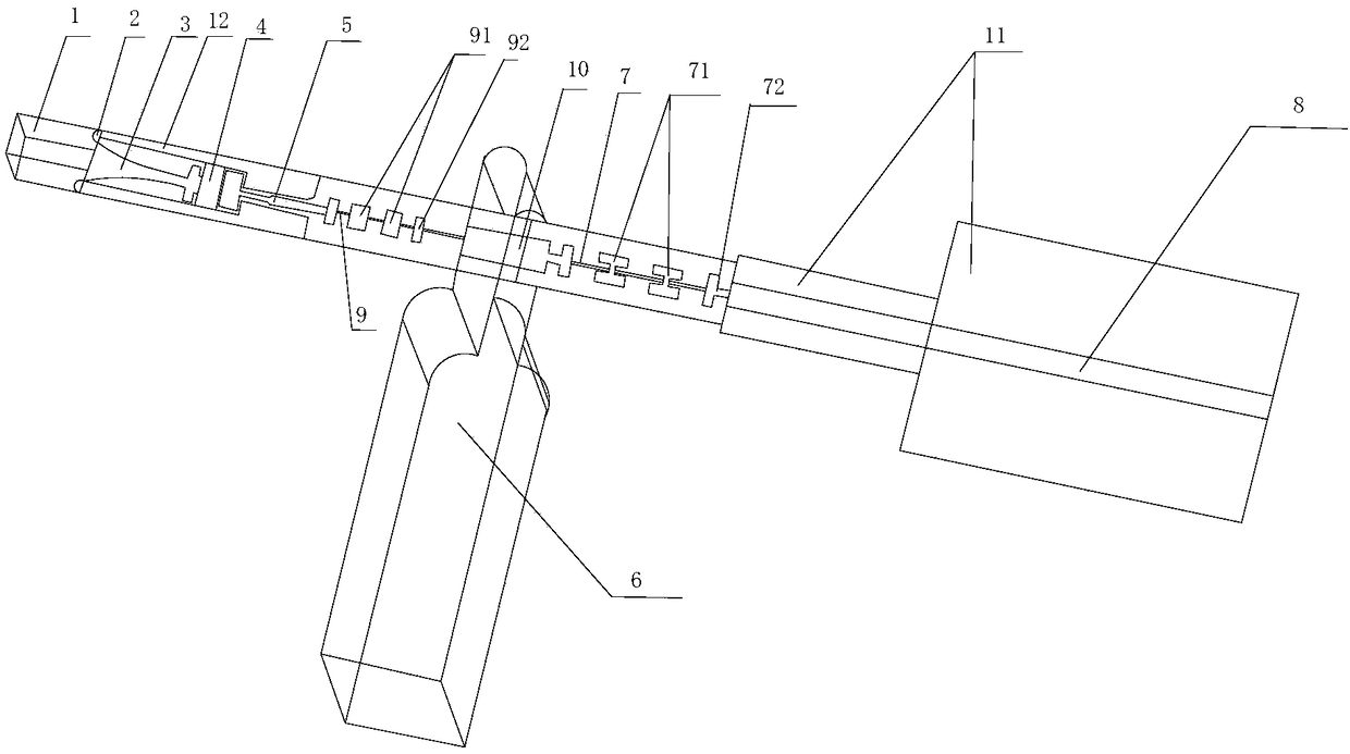
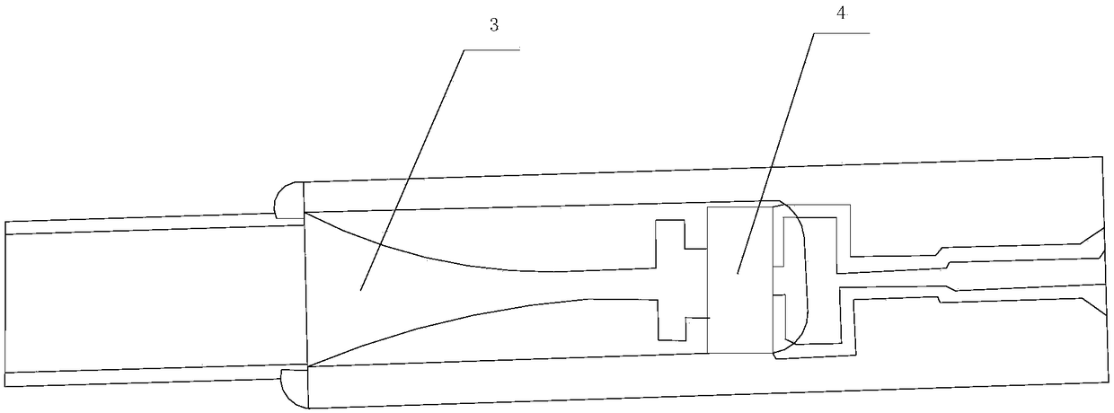
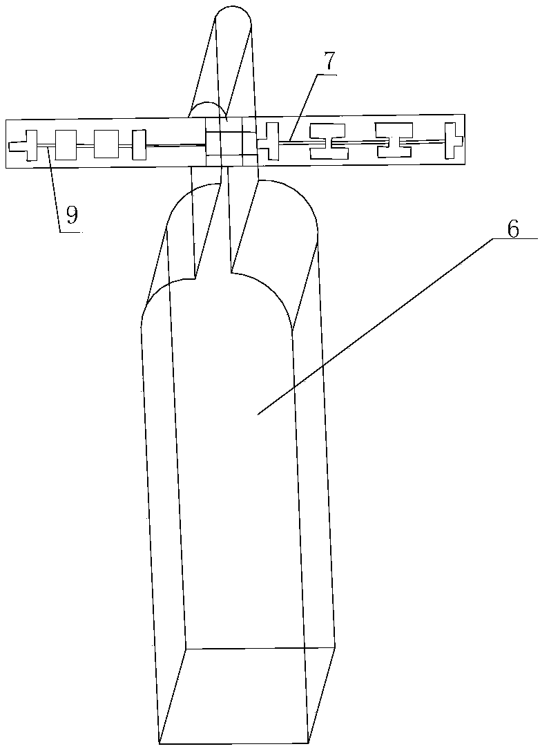
[0036] Such as Figure 1-6 As shown, the present invention includes a terahertz third harmonic mixer based on a fin wire structure, including a metal cavity for placing a circuit, a substrate 12, a radio frequency input circuit and a local oscillator transition circuit, and the substrate 12 Located in the metal cavity, the radio frequency input circuit and the local oscillator transition circuit are located on the substrate 12, the radio frequency input circuit and the local oscillator transition circuit are connected through the local oscillator matching branch 5, and the radio frequency transition waveguide 1 is connected to the input end of the radio frequency input circuit , the RF input circuit includes a fin line 3 and a Schottky diode pair 4, the branch structure of the fin line 3 is directly connected to the metal cavity, the Schottky diode pair 4 is installed on the fin line 3, and the branch structure of the fin line 3 is also connected to the metal cavity The DC gro...

Embodiment 2

[0046] This embodiment is preferably as follows on the basis of Embodiment 1: the fin line 3 includes a main body part and a branch structure connected to each other, the main body part includes an input section and an output section connected in sequence, and the diameter of the end adjacent to the radio frequency transition waveguide 1 of the input section is larger than that on the input section The diameter of the adjacent output section, the two sides of the input section are concave arc lines, and the output section is an inverted T-shaped structure.

[0047] The local oscillator matching stub 5 includes a rectangular transmission line frame, a first parallel transmission line and a second parallel transmission line connected in sequence, the distance between the first parallel transmission lines is smaller than the distance between the second parallel transmission lines, the rectangular transmission line frame and the output section are located at the Schott On both side...

Embodiment 3

[0052] This embodiment is preferably as follows on the basis of the above embodiments: the pair of Schottky diodes 4 is a pair of diodes connected in series in the same direction, and the pairs of diodes connected in series in the same direction are connected by a cross-shaped microstrip line. The diode is the core device of the mixer, and its performance is directly related to the level of frequency conversion loss and the working bandwidth of the mixer. In the terahertz frequency band, the wavelength is very small, and the package size of the diode will have a great impact on its performance. In this scheme, a diode with relatively small cascaded resistance and junction capacitance is selected.

[0053] The substrate 12 is a 50um quartz substrate.

[0054] The intermediate frequency output port 8 is located on a base plate 11, and the base plate 11 includes two interconnected square plates of different sizes. The arrangement of the square board facilitates the connection of...


PUM


Abstract

The invention discloses a fin line structure-based terahertz third-harmonic mixer. The fin line structure-based terahertz third-harmonic mixer comprises a metal cavity used for placing circuits, a substrate, a radio frequency input circuit and a local oscillation transitional circuit; the substrate is positioned in the metal cavity; the radio frequency input circuit and the local oscillation transitional circuit are positioned on the substrate; the radio frequency input circuit and the local oscillation transitional circuit are connected through local oscillation matching branches; the input end of the radio frequency input circuit is connected with radio frequency transitional waveguide; the fin line branch structure arranged on the radio frequency input circuit is directly connected withthe metal cavity; a Schottky diode pair on the radio frequency input circuit is mounted on the fin line; the fin line branch structure is also in grounding connection with a direct current; and the direct current grounding is positioned at the radio frequency input end of the radio frequency input circuit. By adoption of the structure, and by adopting the fin line structure in the radio frequencyport, high grounding of the direct current component in the Schottky diode can be ensured, so that the universality problem of the existing old harmonic mixer can be solved; and the terahertz third-harmonic mixer has less spurious signals and high compression point.

Description

technical field [0001] The invention relates to the field of mixers, in particular to a terahertz third harmonic mixer based on a fin wire structure. Background technique [0002] Terahertz waves refer to electromagnetic waves with a frequency in the range of 0.1THz to 10THz, and a wavelength in the range of 0.03mm to 3mm, which is between microwave and infrared; at both ends of the wave band, they coincide with millimeter waves and infrared light respectively, so that terahertz waves have It has some characteristics that electromagnetic waves in other frequency bands do not have. Before the 1980s, the microwave frequency band and the infrared frequency band became mature after considerable development; however, the terahertz wave band was in the transition zone between macroscopic classical theory and microscopic quantum theory, and at the same time in the transition zone between electronics and photonics. The level of cognition and research techniques are relatively limit...

Claims


Application Information

Patent Timeline
Patent Type & Authority Applications(China)
IPC IPC(8): H01P1/213
CPCH01P1/2135
Inventor 刘宗岳赵小松
Owner 四川众为创通科技有限公司
Learn More