Boiling bed hydrogenation reaction system and boiling bed hydrogenation process method

A technology of hydrogenation reaction and process method, which is applied in chemical instruments and methods, petroleum industry, hydrocarbon oil cracking, etc. It can solve the problems of affecting the effect of hydrogenation reaction, the difficulty of increasing the catalyst loading, and the limited increase of catalyst consumption, so as to achieve the improvement The effect of hydrogenation reaction, the effect of increasing the filling ratio and increasing the volume utilization rate

Pending Publication Date: 2018-06-12
上海竣铭化工工程设计有限公司
View PDF6 Cites 2 Cited by
  • Summary
  • Abstract
  • Description
  • Claims
  • Application Information

AI Technical Summary

Problems solved by technology

[0005] One type is to adopt the mode of oil phase circulation, such as the fluidized bed process described in USRe25,770. The deficiency of this process in practical application is: in order to maintain the liquid-solid separation effect, the amount of catalyst in the reactor should not be too much, and the reactor should use Low efficiency, the utilization rate of industrial ebullated bed reactors is generally only about 40% - the utilization rate generally refers to the percentage of catalyst loading in the reactor volume (excluding head space), and the utilization rate of fixed bed reactors is generally above 90%; There is a large space so that the residence time of the liquid material is too long without catalytic conditions, there is no hydrogenation reaction in this part, and the material is easy to react and coke at high temperature
[0006] Another kind is to arrange three-phase separator in the reactor, carry out gas-liquid-solid separation in the upper part of the reactor, as the ebullating bed reactor that CN02109404.7 introduces, by arranging built-in three-phase separator according to this scheme, can Increase the amount of catalyst, that is, increase the utilization space of the reactor, but in actual use, the increase in the amount of catalyst is limited. If the amount of catalyst increases, the separation effect of the three-phase separator will drop rapidly, and it is actually more efficient than the first type of ebullating bed reactor. The improvement of the efficiency is limited; CN200710012680.9 has further improved the above-mentioned technology. A guide structure is set at the lower part of the three-phase separator, and the guide structure is used to increase the operating flexibility of the three-phase separator, ensure the efficient separation of the three-phase separator, and reduce the catalyst. The amount of carry-over can increase the amount of catalyst storage and the utilization rate of the reactor, but when in use, it is still necessary to set a catalyst dilute phase zone in a certain area at the lower part of the three-phase separator (as shown in the attached figure, the amount of catalyst in this area is very small, basically hydrogenation reaction does not occur), otherwise the separation effect of the three-phase separator still cannot meet the requirements, and the existence of the dilute phase zone will affect the further improvement of the utilization rate of the reactor (although it is pointed out in the specification that the catalyst loading in the reactor cylinder can be 40% to 70% of the reactor volume, but generally only about 50% of the situation can be stable), which also affects the hydrogenation reaction effect, and after the scale of the reactor is enlarged, it is more difficult to increase the catalyst loading, and it is difficult to achieve The effect of the experimental setup
[0007] Although the latter theoretically does not require circulating oil, it will make it difficult for the catalyst to reach a stable boiling state during start-up, shutdown, and abnormal operation, resulting in insufficient operational stability.

Method used


Image

  • Boiling bed hydrogenation reaction system and boiling bed hydrogenation process method
  • Boiling bed hydrogenation reaction system and boiling bed hydrogenation process method

Examples


Embodiment 1

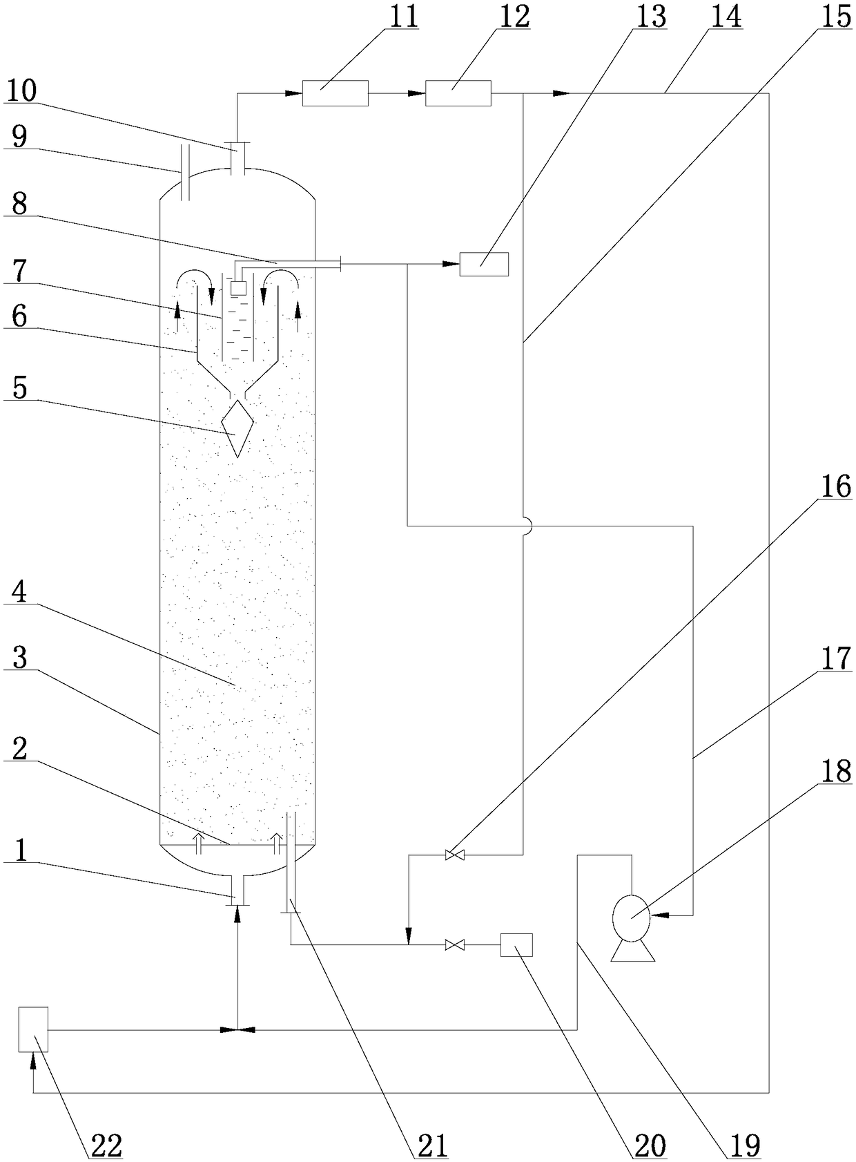
[0031] Example 1 used as figure 1 The ebullating bed hydrogenation reaction system shown. When the hydrogenation reaction is carried out in the reactor of the ebullated bed hydrogenation reaction system, the control valve 16 on the branch 15 between the outlet of the circulating hydrogen compressor and the catalyst discharge pipeline 21 is controlled to make the circulating hydrogen pass through the catalyst continuously or intermittently The discharge pipeline 21 enters the reactor cylinder 3 , and this operation method can effectively avoid the problem of coking of materials in the catalyst discharge pipeline 21 . The amount of circulating hydrogen entering the reactor barrel 3 from the catalyst evacuation pipeline 21 is controlled to be 0.2% of the total circulating hydrogen, while the material flow rate in the catalyst evacuation pipeline 21 is not lower than 0.1 m / s.

[0032] After testing, the catalyst discharge pipeline 21 can be kept unobstructed for a long period of ...

Embodiment 2

[0034] The structure of the ebullating bed hydrogenation reaction system used in embodiment 2 is as follows figure 1 As shown, it includes an ebullating bed hydrogenation reactor, a catalyst removal system, a hydrogen circulation system 12 and a reaction liquid phase effluent circulation system.

[0035] The bottom of the reactor cylinder 3 is provided with a raw material inlet 1 (the raw material includes liquid feedstock oil and hydrogen, which are fed through the reactor feed system 22), the top is provided with a catalyst inlet 9, a gas outlet 10, and the upper part is provided with a liquid outlet . The top in the reactor cylinder 3 is provided with a gas, liquid and solid three-phase separator, and a liquid discharge pipeline 8 is arranged in the liquid phase region of the three-phase separator, and the outlet of the liquid discharge pipeline 8 is the liquid outlet of the reactor cylinder 3, The liquid separated by the three-phase separator is passed into the reaction l...


PUM

PropertyMeasurementUnit
diameteraaaaaaaaaa
heightaaaaaaaaaa
heightaaaaaaaaaa

Abstract

The invention belongs to the technical field of hydrogenation, and particularly relates to a boiling bed hydrogenation reaction system and a boiling bed hydrogenation process method. On one hand, theproblem of coking of parts of pipelines caused by intermittent operation of a catalyst discharge system can be effectively solved. On the other hand, the use ratio of a reactor can be further increased (namely, reserve of catalysts in the reactor is improved), hydrogenation reaction effects are further improved, operating stability of the system is improved, and particularly, stable boiling stateof the catalysts can be maintained in start, in stop and under unusual service conditions.

Description

technical field [0001] The invention relates to a fluidized bed hydrogenation reaction system and a fluidized bed hydrogenation process, belonging to the technical field of hydrogenation. Background technique [0002] Ebullated bed hydrogenation reaction refers to the process of hydrogenation reaction of feedstock oil (mainly in liquid phase) and hydrogen (gas phase) on catalyst (solid phase). Hydrogenation reaction mainly occurs in hydrodesulfurization, hydrodenitrogenation and hydrodeoxygenation , hydrogenation saturation, hydrocracking, etc. The reactor operates in the boiling state of gas, liquid and solid. The catalyst is in a boiling state driven by the raw material oil and hydrogen entering from the bottom of the reactor, which is in a completely different fluid state from the fixed bed reactor. The ebullating bed hydrogenation reaction can process low-quality feed oil with high metal and high asphaltene content. The reaction has the characteristics of small pressure...

Claims


Application Information

Patent Timeline
Patent Type & Authority Applications(China)
IPC IPC(8): B01J8/22C10G45/20C10G47/30
CPCB01J8/007B01J8/1809B01J8/1827B01J8/1863B01J8/22C10G45/20C10G47/30
Inventor 王小英
Owner 上海竣铭化工工程设计有限公司
Why Eureka
Try Eureka